Method and a device for measuring the distance of an object

a technology for measuring distances and objects, applied in measurement devices, surveying and navigation, electromagnetic wave reradiation, etc., can solve the problems of significant affecting the distance measurement, uncontrollable variation in the phase of the signal emitted by the laser light source, and the above-described devices cannot provide an adequate accurate distance measuremen

Inactive Publication Date: 2003-01-28
DATALOGIC
View PDF13 Cites 65 Cited by
  • Summary
  • Abstract
  • Description
  • Claims
  • Application Information

AI Technical Summary

Problems solved by technology

It has been found that the above-described devices cannot provide an adequately accurate measurement of distance, due to a number of drawbacks discussed in greater detail hereinafter.
A first drawback of modulated light devices is that variations in the device operative temperature bring about an uncontrolled variation in the transfer function distance signal/distance, specifically a variation in the phases of respectively the emitted and received signals by the device, which significantly affects the distance measurement.
In order for the system to maintain a constant average output power as temperature changes (a useful condition to keep the read performance of an optical code unvaried), a control circuit is provided whose side effect is that of varying the modulation duty-cycle according to the operative temperature variation; however, this variation in the duty-cycle brings about an uncontrolled variation in the phase of the signal emitted by the laser light source.
Another drawback of modulated light devices is associated to the value of the ratio between the signal detected by the light receiving means and noise (S/N), which ratio may be quite small for objects placed far or near enough and/or dark objects.
A further drawback is associated to the variation of the error of the distance signal according to the optical signal detected by the light receiving means; this is due to operational limitations and to the high sensitivity of the device to changes in reflectance of the objects.
In summary, it has been found that all of the above drawbacks affecting modulated light devices imply an overall error in the distance measurement which can be estimated at about .+-.5%.
This percentage of error restricts the usability

Method used


Image

  • Method and a device for measuring the distance of an object
  • Method and a device for measuring the distance of an object
  • Method and a device for measuring the distance of an object

Examples


Embodiment Construction

Shown at 1 in the drawings is a distance measuring device according to this invention. In a preferred embodiment thereof, the device of this invention constitutes an improved modification of the device disclosed in European Patent Application No. 0 652 530 by the same Applicant.

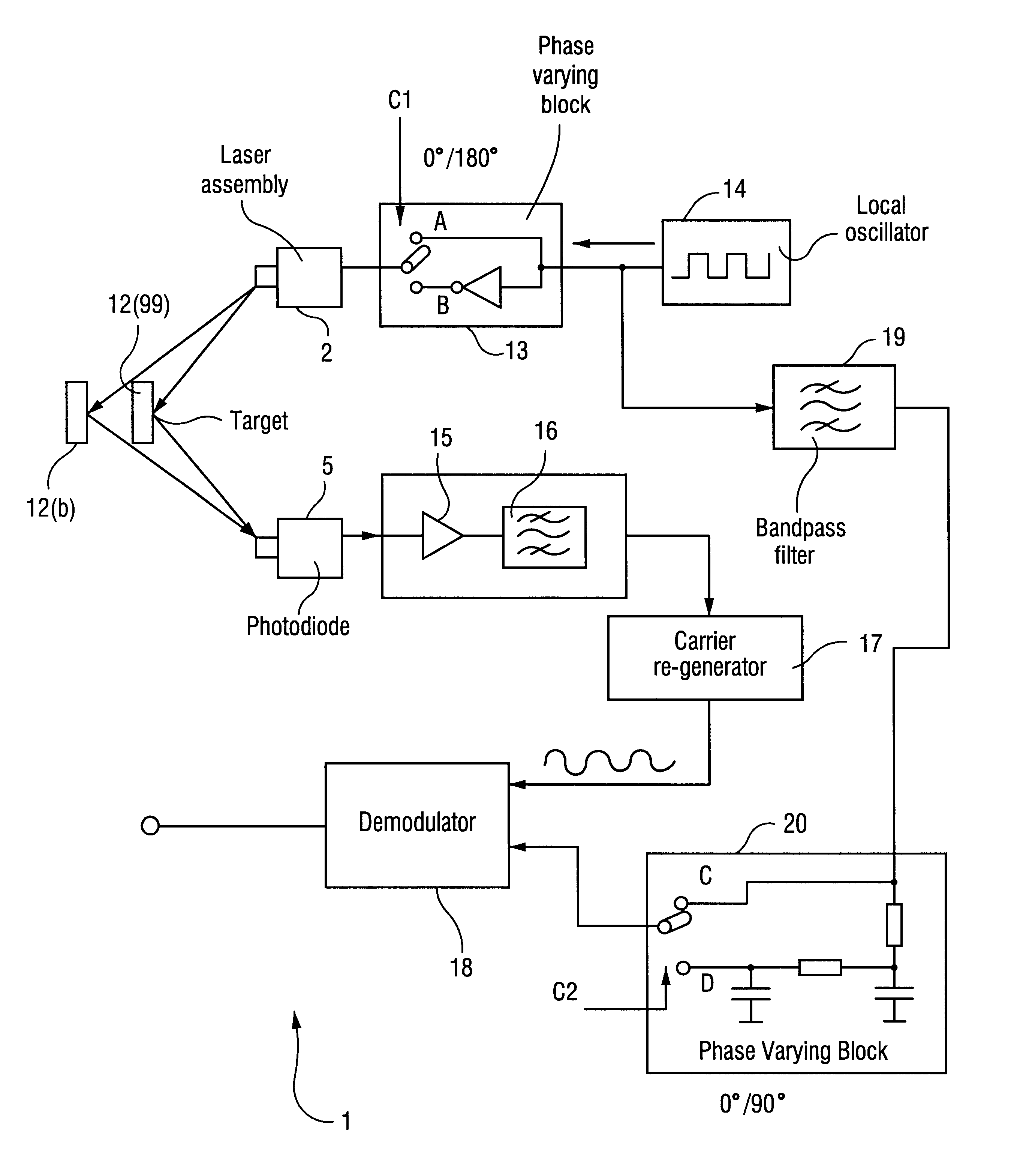
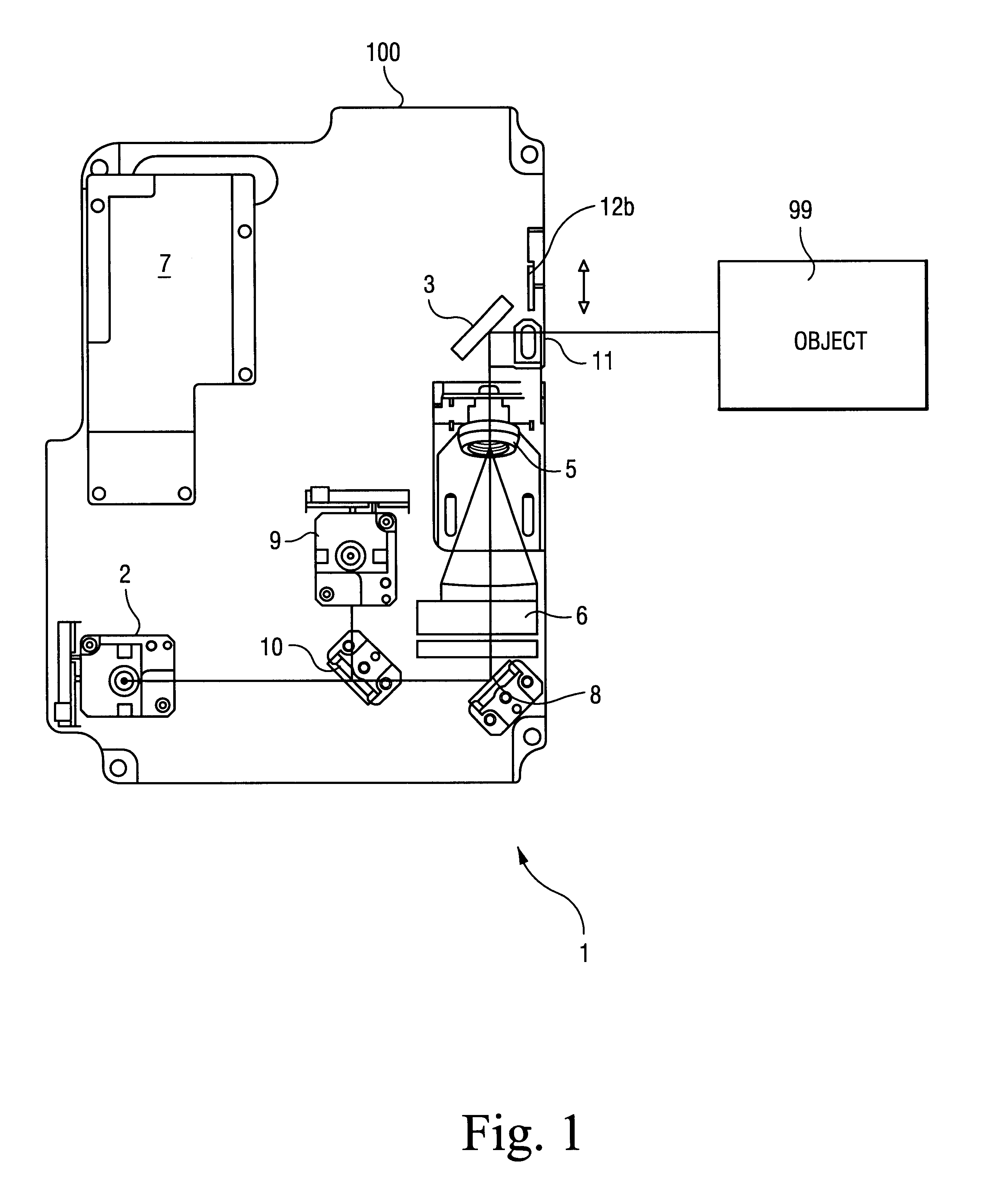
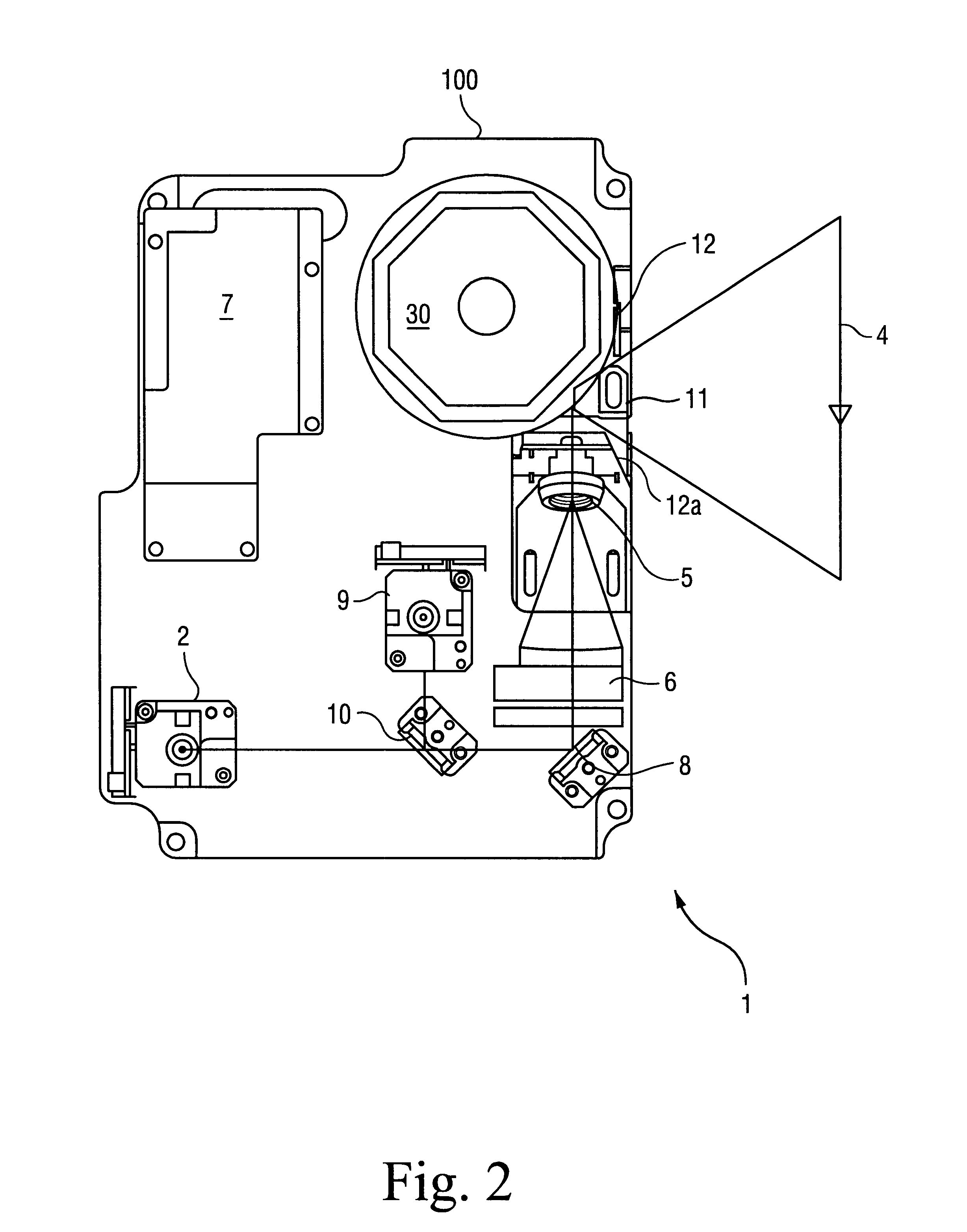
As shown in FIG. 1, the device 1 includes an enclosure 100 housing a first laser assembly 2, of conventional type, which comprises a laser light generator as well as a laser beam focusing optics. The laser assembly 2 is adapted to emit an infrared laser light beam along an emission optical path incorporating a deflecting mirror 8 and a mirror 3 arranged to direct the laser beam onto an object 99 for measuring its distance. The device 1 further comprises a concave receiving mirror 6 arranged to pick up, through the mirror 3, the light diffused by the object 99 along a receiving optical path.

Provided downstream of the concave mirror 6 on the receiving optical path is a receiving photodiode 5 adapted to detect, ...


PUM


Abstract

A method and device (1) are proposed for accurately measuring in a reliable manner the distance of an object (99). The method comprises the steps of emitting a signal (such as a laser light beam), directing the signal to an object (99), detecting the signal diffused by the object (99), and comparing the detected signal with the emitted signal to obtain a comparison signal representing the distances travelled by the emitted signal and the signal diffused by the object (99) (for example, by sending modulated laser light and then measuring the phase difference between the emitted and received signals). The method of the invention is characterized by a step of setting the measuring device in order to define a reference operational configuration within the device. The setting is performed by means of a feedback circuit effective to calibrate at least one operational parameter of the device such that, upon illuminating a reference target (12,12a) which is placed at a known distance a predetermined value of the electric signal generated by the detecting means (5) is obtained.

Description

1. Field of the InventionThe present invention relates to a method and a device for measuring the distance of an object. In particular, the method and device of this invention further enable an optical code provided on the object to be read.2. Discussion of Prior ArtA measurement of the distance of an object from a measuring device is of high utility and sometimes fundamental in several technical fields. This is the case, for example, of all those machining processes where a knowledge of the distance to a surface being machined from the machine tool is necessary for correct positioning of the tools and / or for exact programming of the machine; or all those instances where a knowledge of the distance parameter can allow instruments to be set for optimum processing (e.g., in optics and photography, where the distance parameter is closely related to the focusing problem).Furthermore, a measurement of the distance to an object is often needed in object handling and sorting systems, where...

Claims


Application Information

Patent Timeline
IPC IPC(8): G01S17/00G01S17/36G01S7/48G01S7/497
CPCG01S17/36G01S7/497
Inventor MARCHI, PAOLO
Owner DATALOGIC
Why Eureka
Try Eureka