
Power supply with flux-controlled transformer

a transformer and flux control technology, applied in the direction of automatic control, process and machine control, instruments, etc., can solve the problems of shutting down the process, unable to measure and control the power, current and voltage of individual magnetrons, and eventually degrad

Inactive Publication Date: 2003-03-11
ADVANCED ENERGY IND INC
View PDF10 Cites 16 Cited by
  • Summary
  • Abstract
  • Description
  • Claims
  • Application Information

AI Technical Summary

Problems solved by technology

The result is an insulating coating on both the target and the anode, which will eventually degrade and perhaps even shut down the process when it is powered by a DC supply.
Measurement and control of the power, current and voltage for individual magnetrons is not yet available in sinusoidal AC supplies.
Consequently, the racetracks erode at the same rate.
When a resonant supply is used, an impedance difference between the two magnetrons can result in faster erosion of one target, which unnecessarily reduces the time between preventative maintenance cycles.
Consequently, they have had limited commercial acceptance for the dual magnetron sputtering application.
One problem with asymmetric bipolar pulsed supplies is ground insulation.
First, a low frequency transformer tends to be very large and heavy at high power requirements.
Second, absence of an output transformer reduces the load voltage range of the power supply since the load cannot be matched by changing transformer taps.

Method used


Image

  • Power supply with flux-controlled transformer
  • Power supply with flux-controlled transformer
  • Power supply with flux-controlled transformer

Examples


Embodiment Construction

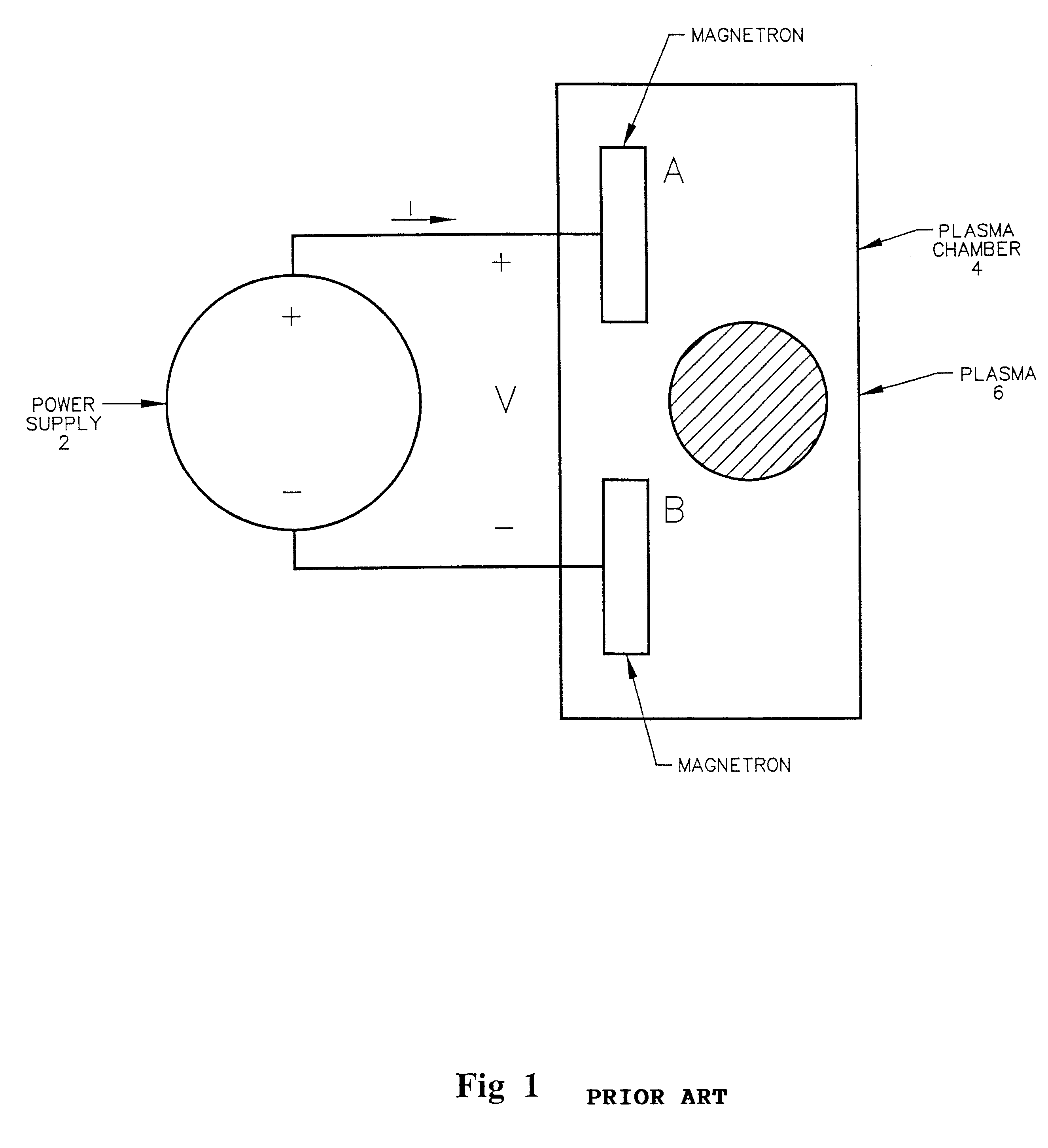
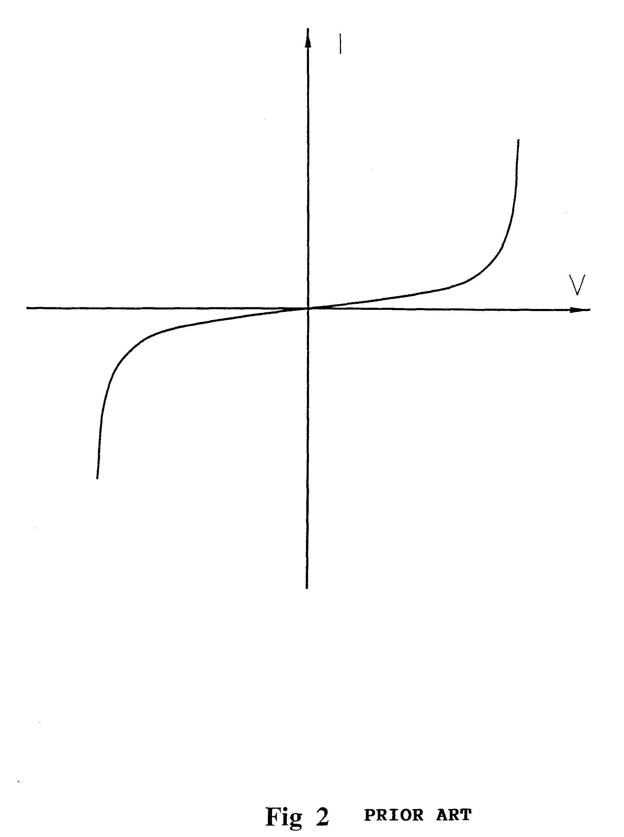
A schematic of a dual magnetron sputtering arrangement driven by a power supply with an output transformer 8 is shown in FIG. 4. The transformer provides the functions of isolation and voltage level transformation. The possibility of different voltages and currents for each polarity can imply the possibility of saturating the transformer since the average voltage at the transformer primary usually must equal zero to keep the transformer from saturating. Isolation from the mains is required because the mains power and the plasma chamber are typically referenced to earth ground. Failure to provide isolation results in an undesired electrical current path. This will cause unpredictable behavior from the process and possible failure of the power supply. The power supply output current and the voltage-current (V-I) characteristics of the process load determine the output voltage. It is often desirable to drive a process whose operating voltage falls outside the capabilities of the power ...


PUM

PropertyMeasurementUnit
refractive indexaaaaaaaaaa
voltageaaaaaaaaaa

Abstract

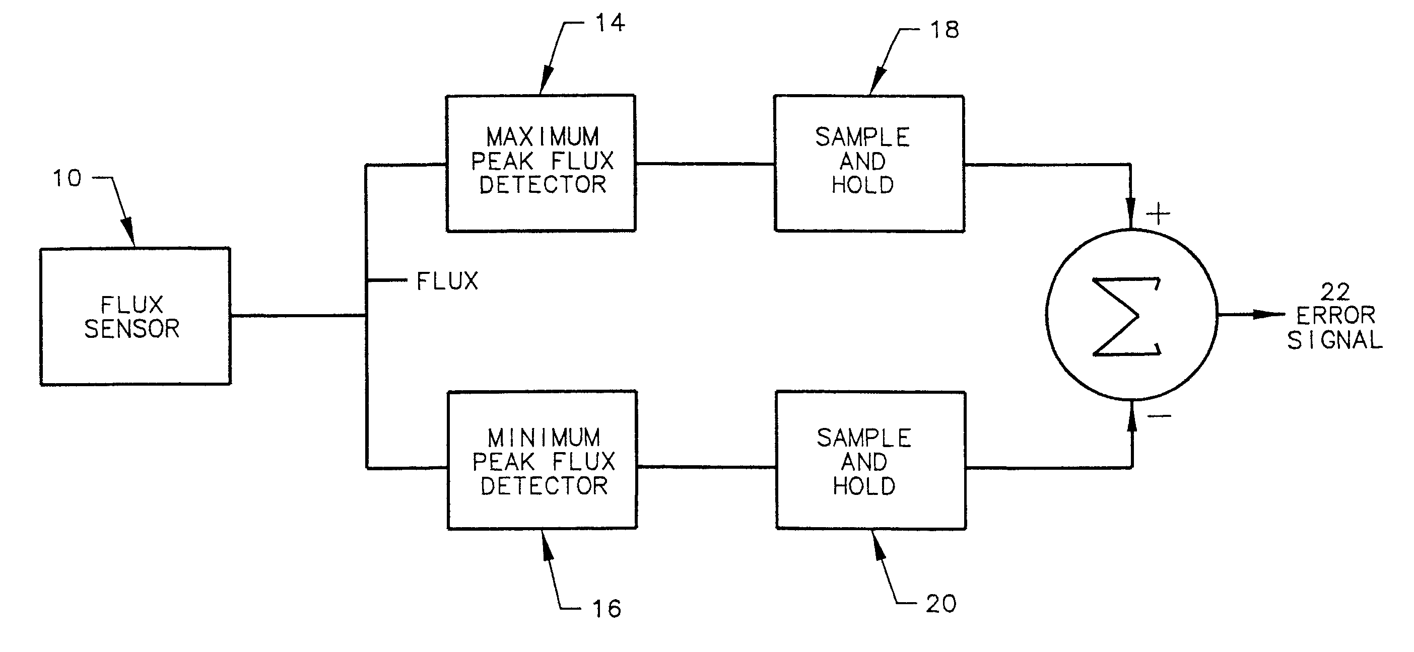
There is provided by this invention an apparatus and method for generating voltage pulses to first and second magnetron devices in a plasma chamber. An isolation transformer is connected to a pulsed DC power supply having a flux sensor, such as a Hall effect sensor, in close proximity to its air gap to monitor the transformer flux. A control circuit is connected to the flux sensor to control the duty cycle of the transformer by controlling the flux of the transformer such that the maximum and minimum peak transformer fluxes are equal in magnitude and opposite in sign to prevent saturation.

Description

1. Field of the InventionThe present invention relates generally to the control of the delivery of power in a variety of applications, and more particularly to methods and systems to deliver and control pulsed power as may be applicable to plasma thin film processing and other applications.2. Brief Description of the Prior ArtThin film layer systems are commonly deposited on glass or polymer substrates with a large area coater. These layer systems are often an implementation of an optical filter. These filters use a combination of interference effects and the transmission and reflection spectra of the discrete metal and dielectric layers to arrive at their composite spectral transmission and absorption characteristics. The metallic layers, commonly titanium, silver, nichrome, aluminum or stainless steel, are typically sputtered with a magnetron operating in the metallic mode in an argon gas environment and powered by a DC supply as described in the book by R. J. Hill, S. J. Nadel, "...

Claims


Application Information

Patent Timeline
Patent Type & Authority Patents(United States)
IPC IPC(8): H01F27/00H01F27/40H01J37/34H01J37/32H01F30/06H01F19/00H01F19/08H01L21/3065H02M1/40H02M7/48H02M9/02
CPCH01F27/402H01F30/06H02M7/48H01J37/3444H02M1/40H01J37/3405H01F2019/085
Inventor KOVALEVSKII, DMITRIKISHINEVSKY, MICHAELCHRISTIE, DAVID J.
Owner ADVANCED ENERGY IND INC
Learn More