Method and apparatus for detecting and isolating a rupture in fluid distribution system

Inactive Publication Date: 2003-03-18
MPR ASSOC
View PDF20 Cites 31 Cited by
  • Summary
  • Abstract
  • Description
  • Claims
  • Application Information

AI Technical Summary

Benefits of technology

The methods and apparatus of the present invention incorporate valves having processors pre-programmed with rupture path logic steps for sensing and isolating damaged portions of fluid handling systems and restoring intact, undamaged sections to service, without intervention by shipboard personnel. In the methods of the present invention, the rupture is sensed and automatically isolated by cutting off damaged portions using only the information available at each valve. Use of global system information such as pre-damage configuration information from a remote supervisory or master control system preferably enhances system reliability and response time, but is not required for system operation, in the method of the present invention.
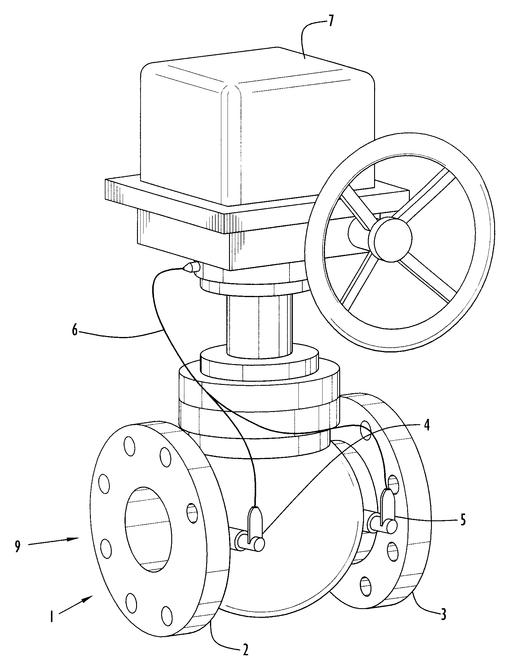
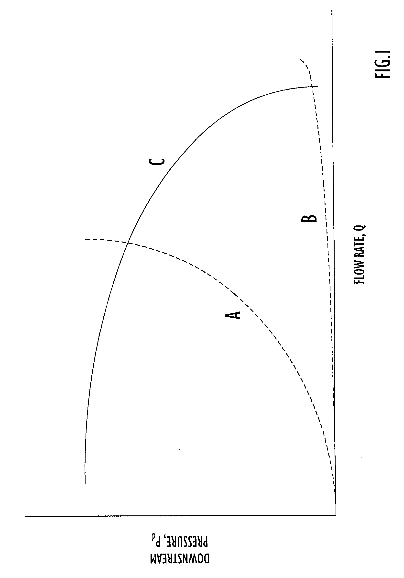
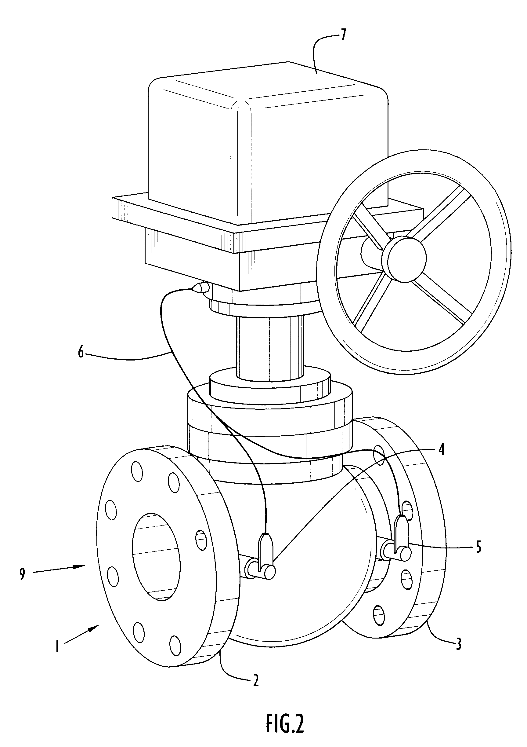
Each valve utilized in the invention includes first and second pressure sensors at or near the valve inlet and valve outlet, respectively, to measure a fluid characteristic, such as rupture resistance, in the fluid handling system pipe network. Optionally, each valve may also include a flow rate sensor for measuring the fluid flow rate at or near the valve. A fluid characteristic is determined from either the pressure readings or the pressure and flow rate reading

Problems solved by technology

Neither technique is practical for rapid and dependable detection of significant leaks or ruptures in the piping in situations where one or more sensors may be damaged and unable to provide detection inform

Method used


Image

  • Method and apparatus for detecting and isolating a rupture in fluid distribution system
  • Method and apparatus for detecting and isolating a rupture in fluid distribution system
  • Method and apparatus for detecting and isolating a rupture in fluid distribution system

Examples


example 2

FIGS. 5a-5c depict a looping piping system 20 having the same A-F smart valve and P1-P8 pump configuration as depicted in FIGS. 4a-4d, with an additional line branching from the loop including smart valve I. All of the smart valves are open in FIG. 5a, and pumps P3 and P6 are the only pumps online (marked accordingly in FIGS. 5a-5c to show online status). Downstream from valve I is a branching network of pipes 21 that deliver fluid to selected areas throughout a structure that houses piping system 20.

The input information for valves A-H is the same as that which is set forth in Example 1. Valve I utilizes the same input information with the exception of the Nma, value. The pressurized fluid supply source for valve I and the branch line it is on is at the branch pipe connection to the main line or loop supplying fluid to the branch line. For valve I, the single fluid supply source is at the T-branch location designated as 22 in FIG. 5a, such that N.sub.max =N.sub.valve =0 for valve I...

example 3

FIGS. 6a-6e depict a piping system 30 having the same A-H smart valve and P1-P8 pump configuration as the system in FIGS. 4a-4d. System 30 also has two cross connecting portions, wherein one cross connecting portion includes valve J and the other cross connecting portion includes valve K, resulting in multiple loops within the system. The input information for the smart valves is the same as that which is set forth in Example 1, with the exception of the N.sub.max value. A system having multiple cross connects will result in several different options available for a determining valve locations. In this example, the lowest number of valves separating a pump from a valve was selected as the convention. Utilizing this numbering convention, the highest possible valve location number is 4 (i.e., N.sub.max =4). FIG. 6a represents system 30 operating under normal conditions in which all valves are open and pumps P3 and P6 are online (marked accordingly to show their online status).

FIG. 6b ...


PUM


Abstract

Rupture path logic methods of detecting, locating and isolating ruptures within a fluid piping system are disclosed, wherein a rupture within a piping system can be detected and isolated based solely upon local pressure and flow rate measurements at individual valves within the system without the need for communication of measured fluid data between valves at various locations throughout the system. A fluid characteristic is determined individually for each valve based upon the pressure and flow rate measurements at the valve, and that fluid characteristic is compared with set point fluid characteristic information to determine whether each valve is on a fluid path between a fluid supply source and a rupture. Upon detecting a rupture, valves detected as being on such a fluid path are automatically closed within the system in an order of valves furthest from all online fluid supply sources closing first, thereby ensuring eventual isolation of the rupture while allowing intact sections of the piping system to remain open and operational. An automatic rupture detection and isolation fluid piping system is also disclosed that utilizes rupture path logic methods to isolate detected ruptures within the system.

Description

1. Technical FieldThe present invention relates to methods and related apparatus for automatically and effectively isolating ruptures in fluid piping systems without the need for shutdown or manual assistance, thereby allowing such piping systems to continue operating during the detection and isolation of system ruptures.2. Discussion of the Related ArtFluid distribution systems often include loop networks and / or branch networks with extended segments of piping or tubing through which flow is controlled using one or more valves. Typically, the valves are actuated by electric, pneumatic or hydraulic actuators which respond to control signals generated from a remote controller. Such fluid control systems frequently distribute cooling fluid through energy generation or energy management systems or are included as part of an automated fire control system as might be found aboard sea vessels.In particular, shipboard firemain systems must be designed to operate in an automated manner sinc...

Claims


Application Information

Patent Timeline
IPC IPC(8): G01F25/00F17D5/00F17D5/02G01M3/28
CPCF17D5/02G01M3/2815G01M3/2807G01F25/00Y10T137/7759Y10T137/7782Y10T137/86397
Inventor LESTINA, THOMASBRADLEY, MELISSADOWNS, RYANRUNNERSTROM, ERIC
Owner MPR ASSOC
Why Eureka
Try Eureka