Power down circuit detecting duty cycle of input signal

a power-down circuit and input signal technology, applied in pulse manipulation, pulse technique, instruments, etc., can solve the problems of affecting and reducing the detection efficiency of power-down signals

Inactive Publication Date: 2003-04-22
DIODES INC
View PDF18 Cites 54 Cited by
  • Summary
  • Abstract
  • Description
  • Claims
  • Application Information

AI Technical Summary

Problems solved by technology

Oftentimes the number of pins on a chip is limited, and using one of the few available pins for a power-down signal is undesirable.
A problem can occur when using a frequency detector to detect a slowed or stopped clock.
However, as th

Method used


Image

  • Power down circuit detecting duty cycle of input signal
  • Power down circuit detecting duty cycle of input signal
  • Power down circuit detecting duty cycle of input signal

Examples


Embodiment Construction

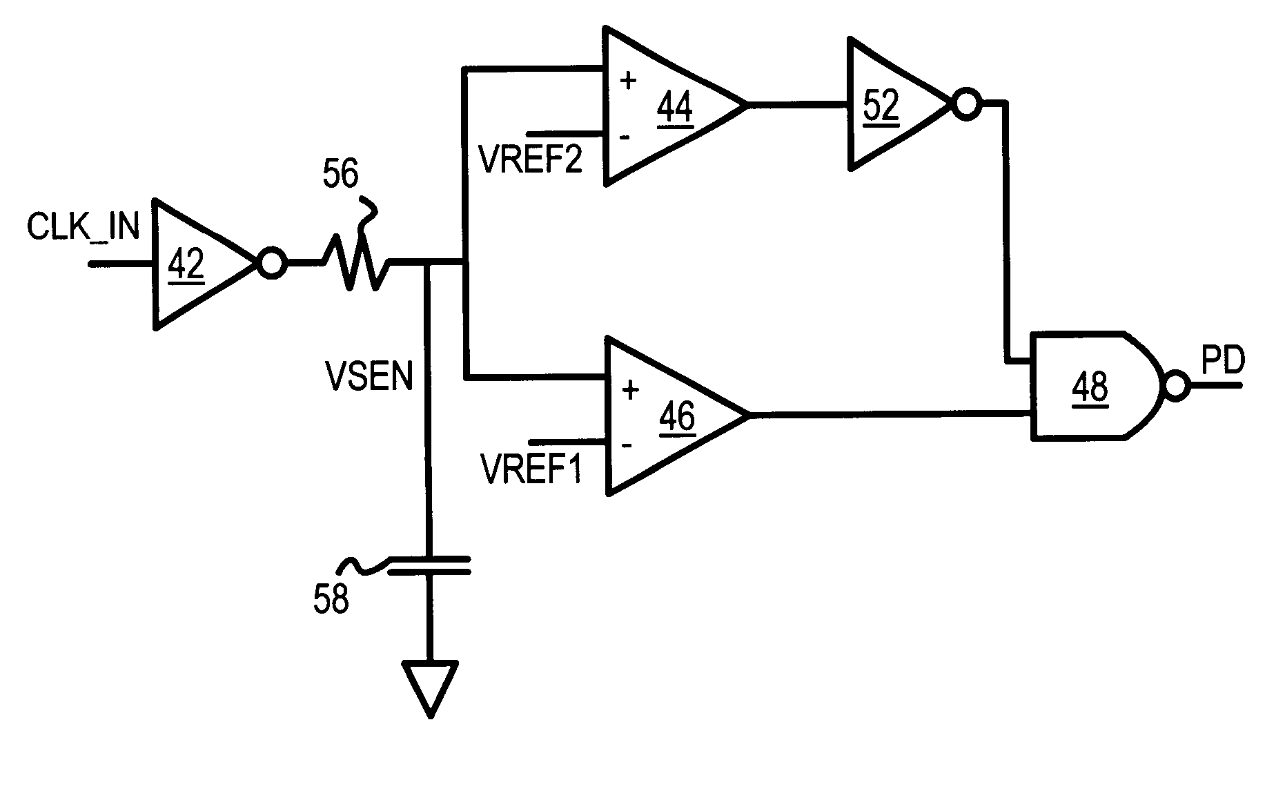
Several other embodiments are contemplated by the inventors. Additional logic gates, buffers, and latches can be added to the circuits shown. Signals can be inverted and gates adjusted using DeMorgan's theorem. Clock inputs not driven fully to Vcc and ground can also be used, and the reference voltages can be adjusted accordingly. The resistance and capacitance values in the filter can have a variety of values, depending on the clock frequency and number of clock periods to average. More complex filters can be used. Op amps can be used for comparators, such as for comparators 44, 46.

The clock input may be buffered or inverted before being applied to the detector, and the power down signal may be active high or active low, and may itself be buffered, inverted, and gated before being applied to various blocks. The inputs to a comparator can be reverse rather than use a separate inverter. The sub-system blocks powered down can be on the same substrate as the detector or can be include ...


PUM


Abstract

When the clock is stopped during a power-down mode, a clock duty-cycle detector asserts a power-down signal. The clock input is filtered to produce an average clock voltage over several clock periods. The average clock voltage is compared to an upper reference voltage to determine when the clock's duty cycle (high pulse-width percent) is above an upper limit. The average clock voltage is also compared to a lower reference voltage to determine when the clock's duty cycle is below a lower limit. When the clock's duty cycle is above the upper limit or below the lower limit the power-down signal is activated by logic. The logic disables the power-down signal when the clock's duty cycle is between the upper and lower limits. High-frequency clock glitches do not falsely trigger a power-up, since glitches are usually narrow and not sufficiently wide to reach the lower limit.

Description

BACKGROUND OF INVENTIONThis invention relates to integrated circuits (IC's), and more particularly to clock power-down detection.Low-power and battery-operated electronic systems often are able to power down all or parts of the system to reduce power consumption. Subsystems can be partially powered down by stopping a clock input to the subsystem, or more fully powered down by asserting a power-down or enable input to the subsystem.FIG. 1 shows a prior-art chip with separate clock and power-down inputs. Chip 10 could be a subsystem such as a memory, or part of a subsystem such as one memory chip on a memory module, or a network controller on a network card. A clock is input to chip 10, and a separate power-down signal is applied to an enable input (.about.EN) of chip 10. When the power-down signal is active (high), chip 10 is disabled and its power consumption is reduced. The clock to chip 10 may or may not be stopped.Oftentimes the number of pins on a chip is limited, and using one ...

Claims


Application Information

Patent Timeline
IPC IPC(8): G06F1/32H03K5/19
CPCG06F1/3203H03K5/19Y02B60/1217Y02D10/00
Inventor CHEUNG, JACKY HUNG-YANHATTORI, HIDE
Owner DIODES INC
Why Eureka
Try Eureka