A number of spinal disorders are caused by traumatic spinal injuries,
disease processes, aging processes, and congenital abnormalities that cause pain, reduce the flexibility of the spine, decrease the
load bearing capability of the spine, shorten the length of the spine, and / or distort the normal curvature of the spine.
With aging, the
nucleus becomes less fluid and more viscous and sometimes even dehydrates and contracts (sometimes referred to as "isolated disc
resorption") causing
severe pain in many instances.
In addition, the annulus tends to thicken, desiccate, and become more rigid, lessening its ability to elastically deform under load and making it susceptible to fracturing or fissuring.
The
fissure itself may be the sole morphological change, above and beyond generalized degenerative changes in the
connective tissue of the disc, and disc fissures can nevertheless be painful and debilitating.
Another disc problem occurs when the disc bulges outward circumferentially in all directions and not just in one location.
Mechanical stiffness of the joint is reduced and the spinal motion segment may become unstable shortening the
spinal cord segment.
As the disc "roll" extends beyond the normal circumference, the
disc height may be compromised, and foramina with nerve roots are compressed causing pain.
Patients who suffer from such conditions can experience
moderate to severe distortion of the thoracic skeletal structure, diminished ability to bear loads, loss of mobility, extreme and debilitating pain, and oftentimes suffer neurologic deficit in
nerve function.
Controversy exists regarding the preferred method of performing these fusions for various conditions of the spine.
This procedure has many complications including
severe pain and spasm, which may last up to several weeks following injection.
Although damaged discs and vertebral bodies can be identified with sophisticated diagnostic imaging, the
surgical procedures are so extensive that clinical outcomes are not consistently satisfactory.
As a result, the
spinal column can be further weakened and / or result in
surgery induced pain syndromes.
Only a
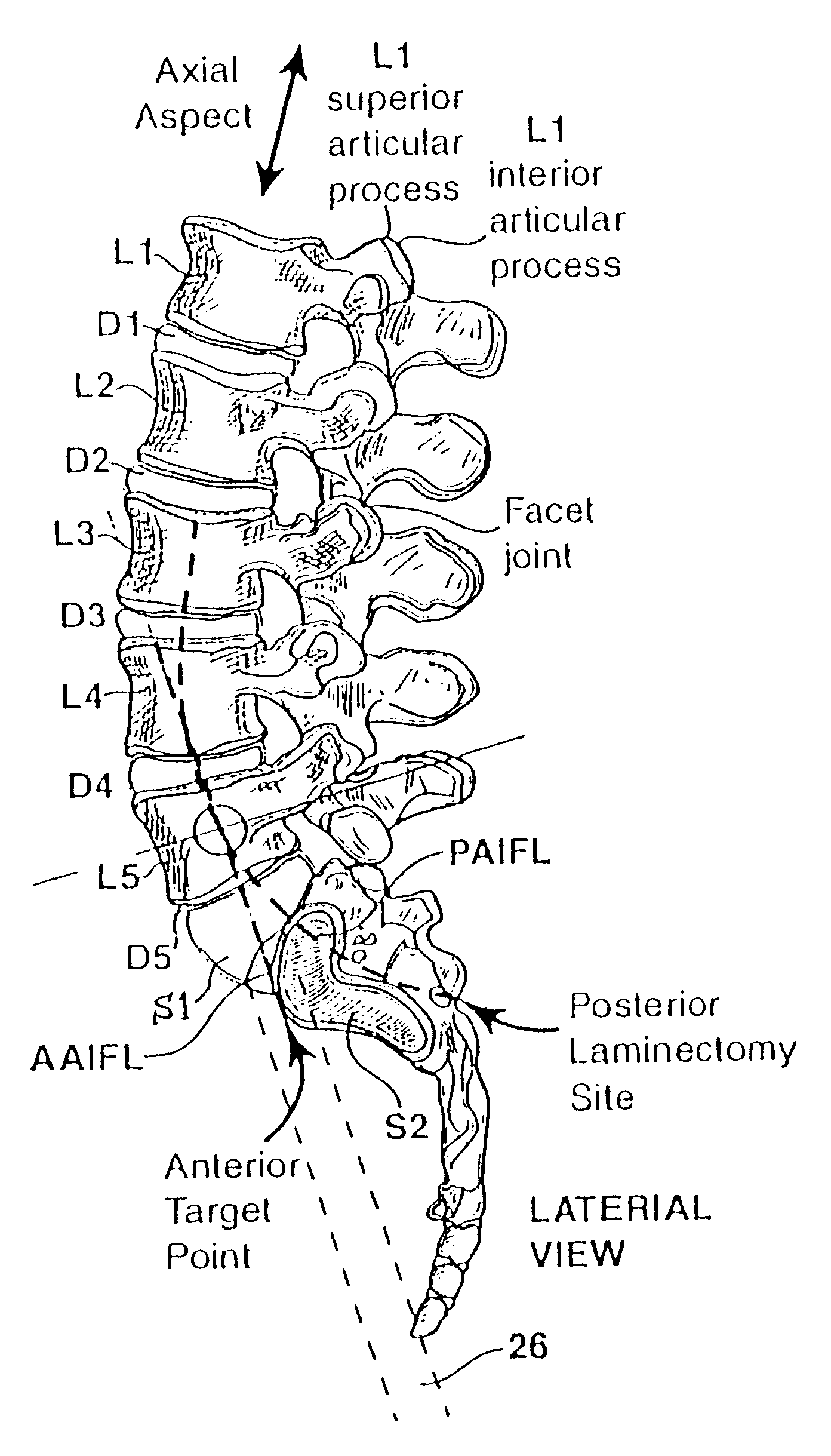
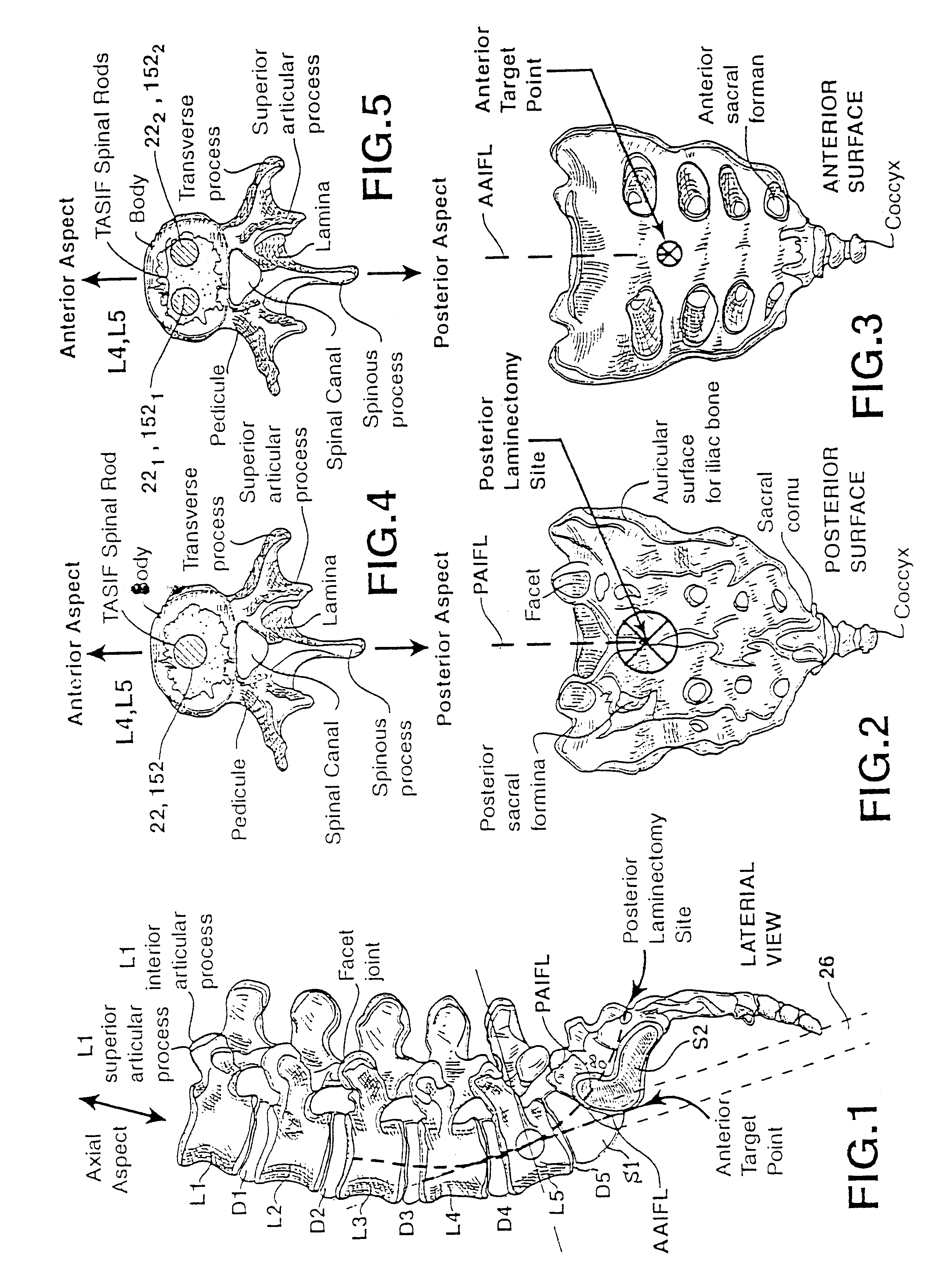
limited access to and alignment of S1 and L5 can be achieved by this approach because the distal ends of the straight bore and shaft approach and threaten to perforate the
anterior surface of the L5
vertebral body.
Thus, disadvantages to the present implants and surgical implantation techniques remain concerning the implantation procedures and involving post-
surgical failure necessitating re-operation.
The exposed ends of the cage or side by side installed cages can irritate nerves causing pain to emerge again.
The large laterally drilled hole or holes can compromise the integrity of the vertebral bodies, and the
spinal cord can be injured if they are drilled too posteriorly.
The endplates of the vertebral bodies, which comprise very hard
cortical bone and help to give the vertebral bodies needed strength, are usually weakened or destroyed during the drilling.
The telescoping causes the length of the
vertebral column to shorten and can cause damage to the spinal cord and nerves that pass between the two adjacent vertebrae.
Since the pedicles of vertebrae above the second
lumbar vertebra (L2) are very small, only small
bone screws can be used which sometimes do not give the needed support to stabilize the spine.
These rods and screws and clamps or wires are surgically fixed to the spine from a
posterior approach, and the procedure is difficult.
These approaches are criticized as failing to provide adequate medial-lateral and rotational support in the '899 patent.
These approaches involve considerable damage to ligaments and tissue in the anterior access to the vertebral bones.
The use of radiopaque
metal cages or other
metal implants also makes it difficult to image the
disc space with radiographic
imaging equipment to assess the degree of fusion achieved by
bone growth between the vertebral bodies separated by the cages.
The filling of the bag under pressure tends to distract, i.e., to separate, the adjoining vertebral bodies to the physiologic separation that would be provided by the undamaged disc.
The posterolateral or anterior
lateral approach is necessitated to correct the severe
spondylolisthesis displacement using the reduction tool and results in tissue injury.
Vertebral compression fractures of healthy vertebral bodies can also occur due to injury.
In most cases, the corset is not worn because the patient suffers much discomfort and oftentimes greater discomfort than that due to the fracture of the vertebral body.
As a result, the
spinal column can be further weakened and / or result in
surgery induced pain syndromes.
Only a
limited access to and alignment of S1 and L5 can be achieved by this approach because the distal ends of the straight bore and shaft approach and threaten to perforate the
anterior surface of the L5 vertebral body.
The sheath or guide is advanced through the bore as the bore is made, making it not possible for the user to adjust the curvature of the bore to track physiologic features of the bone that it traverses.

