Dynamic pipe staging adder

a technology of adder and pipe, applied in the field of information processing systems, can solve the problem of excessive processing cycle and the inability to execute many instructions

Inactive Publication Date: 2003-05-06
IBM CORP
View PDF8 Cites 6 Cited by
  • Summary
  • Abstract
  • Description
  • Claims
  • Application Information

AI Technical Summary

Problems solved by technology

Consequently, excess processor cycles are present to execute many instructions.

Method used


Image

  • Dynamic pipe staging adder
  • Dynamic pipe staging adder
  • Dynamic pipe staging adder

Examples


Embodiment Construction

System Description

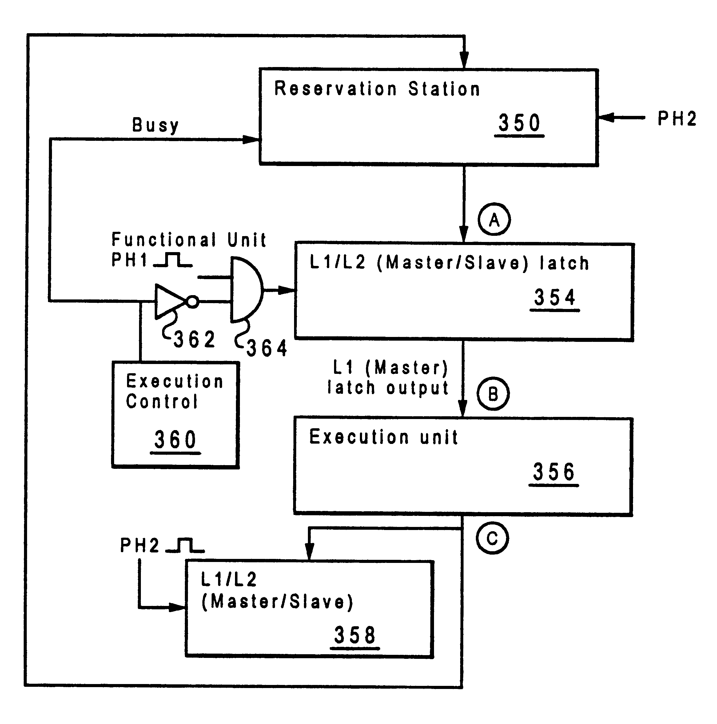
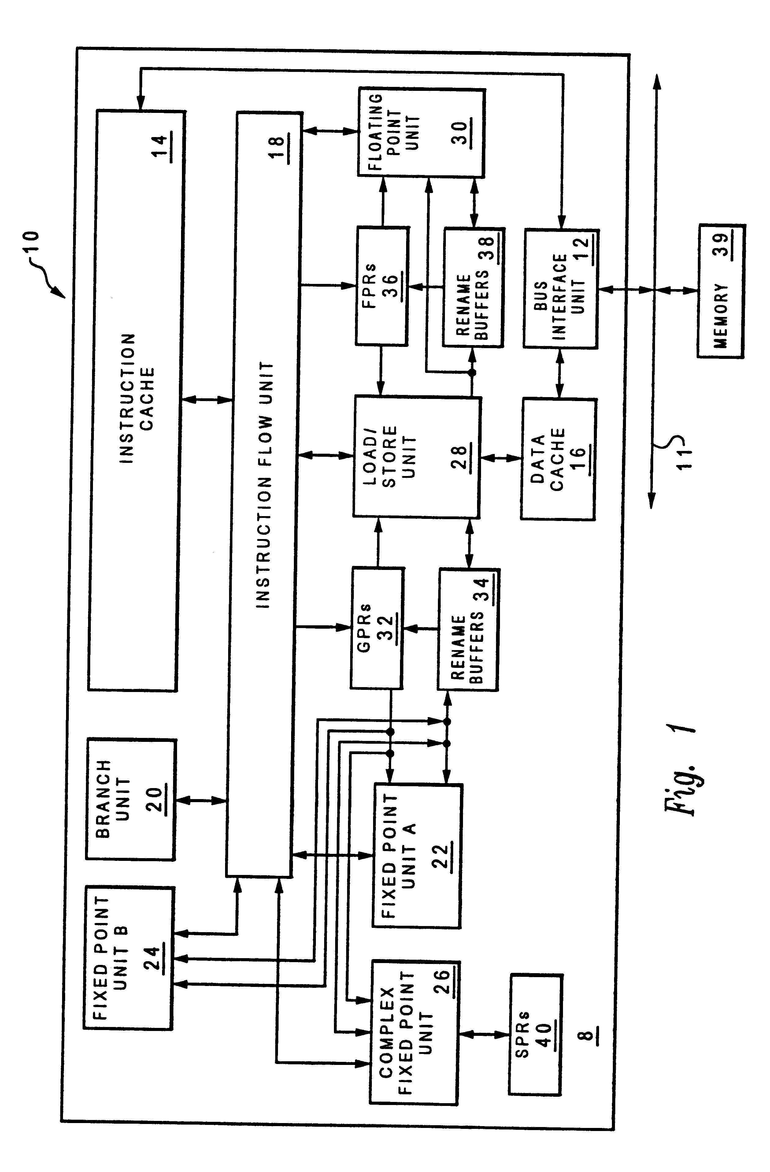
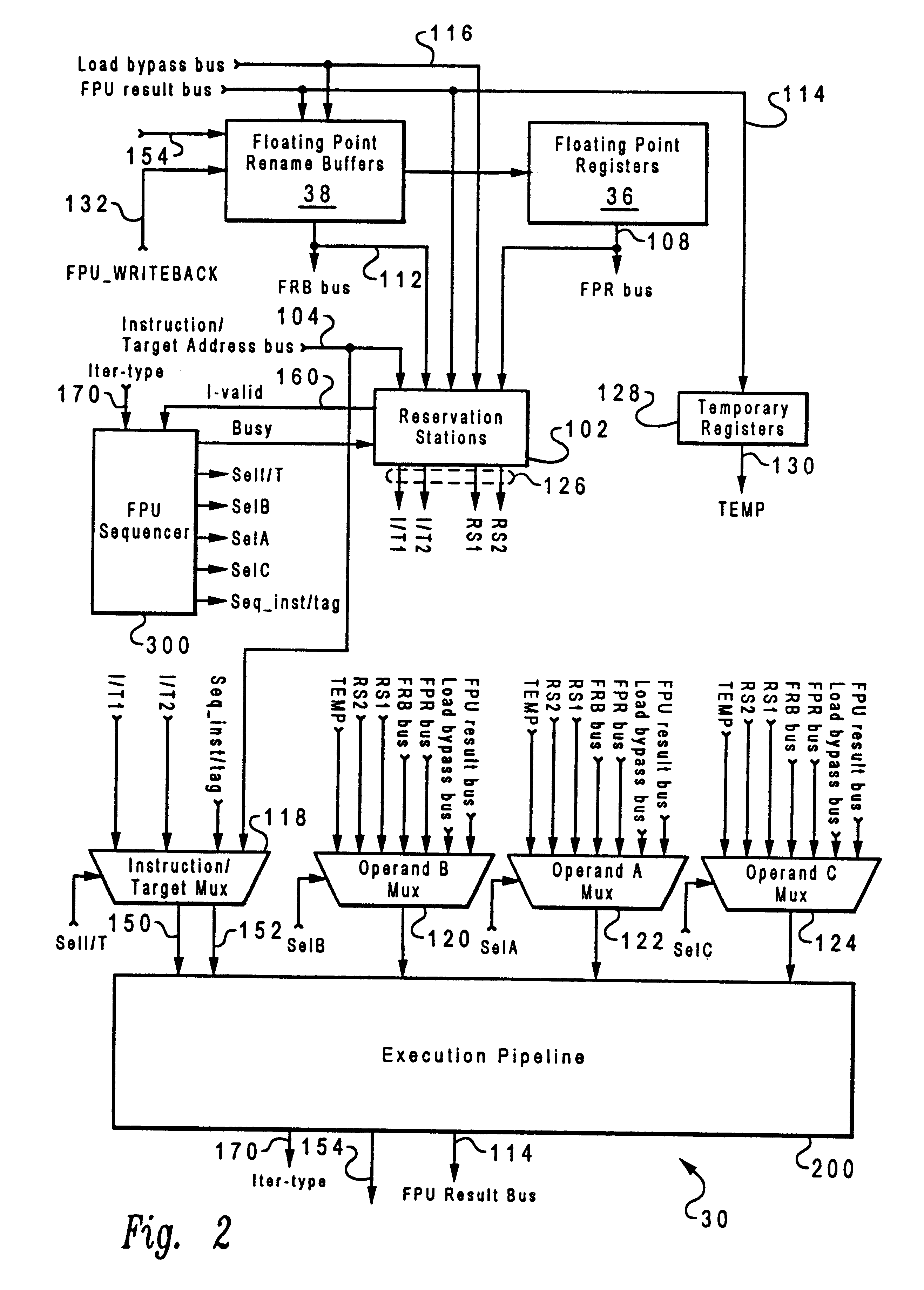
In FIG. 1 and FIG. 2, all information paths are shown with a single line and each such data path transfers multiple bits of information. Likewise, unless otherwise specified, all control signals, registers, multiplexers, and other sections of system 10 operate in response to multiplexed bits of information.

With reference to FIG. 1, a block diagram of a system, indicated generally at 10, for processing information is illustrated according to the present invention. A processor 8 of system 10 is a single integrated circuit superscalar microprocessor. Accordingly, as discussed further hereinbelow, system 10 includes various units, registers, buffers, memories, and other sections, all of which are formed by integrated circuitry. Also, in the preferred embodiment, system 10 operates according to reduced instruction set computing ("RISC") techniques. As shown in FIG. 1, a system bus 11 is connected to a bus interface unit ("BIU") 12 of system 10. BIU 12 controls the trans...


PUM


Abstract

The present invention provides a method and apparatus for processing instructions in which the time allowed for the execution of an instruction is dynamically allocated. The allocation of time for execution of instruction occurs after the instruction is sent to the execution unit. The execution unit determines whether it can complete the instruction during the current processor cycle. In response to an ability to complete the instruction within the current processor cycle, the execution unit issues a busy signal to the reservation station. The reservation station continues to hold the next instruction until the execution until is capable of processing it.

Description

1. Technical FieldThe present invention relates generally to systems for processing information and in particular to an improved method and apparatus for executing instructions. Still more particularly, the present invention relates to an improved method and system for executing instructions requiring different lengths of time for execution.2. Description of the Related ArtA superscalar microprocessor allows for the out-of-order execution of instructions. In such a microprocessor, a buffer called a "reservation station" is employed to place op codes and operands prior to being sent to an execution unit. In this type of microprocessor instructions are sent to the execution unit when a determination is made that all of the operands are available. Instructions are not required to be executed in program order in such a microprocessor system. Whenever an instruction has all its operands ready, the instruction is selected to be sent for execution by the reservation station. Once the instr...

Claims


Application Information

Patent Timeline
Patent Type & Authority Patents(United States)
IPC IPC(8): G06F9/30G06F9/38
CPCG06F9/3836G06F9/3857G06F9/384G06F9/3875G06F9/3858
Inventor HEASLIP, JAY
Owner IBM CORP
Why Eureka
Try Eureka