Ophthalmic instrument having an integral wavefront sensor and display device that displays a graphical representation of high order aberrations of the human eye measured by the wavefront sensor

a wavefront sensor and ophthalmology technology, applied in the field of ophthalmology instruments, can solve the problems of limiting the resolution of the camera, impairing vision, and significantly increasing the complexity and cost of the system, so as to improve the dynamic range of operation, reduce the complexity and cost of the instrument, and expand the potential useful applications of the instrument.

Inactive Publication Date: 2003-06-03
ADAPTIVE OPTICS ASSOC
View PDF48 Cites 122 Cited by
  • Summary
  • Abstract
  • Description
  • Claims
  • Application Information

AI Technical Summary

Benefits of technology

FIG. 1 shows a horizontal cross section of the human eye. The eye is nearly a sphere with an average diameter of approximately 20 mm. Three membranes--the cornea and sclera outer cover, the choroid and the retina--enclose the eye. The cornea 3 is a tough transparent tissue that covers the anterior surface of the eye. Continuous with the cornea 3, the sclera 5 is an opaque membrane that encloses the remainder of the eye. The choroid 7 lies directly below the sclera 5 and contains a network of blood vessels that serves as the major source of nutrition to the eye. At its anterior extreme, the choroid 7 includes a ciliary body 9 and an iris diaphragm 11. The pupil of the iris diaphragm 11 contracts and expands to control the amount of light that enters the eye. Crystalline lens 13 is made up of concentric layers of fibrous cells and is suspended by fibers 15 that attach to the ciliary body 9. The crystalline lens 13 changes shape to allow the eye to focus. More specifically, when the ciliary muscle in the ciliary body 9 relaxes, the ciliary processes pull on the suspensory fibers 15, which in turn pull on the lens capsule around its equator. This causes the entire lens 13 to flatten or to become less convex, enabling the lens 13 to focus light from objects at a far away distance. Likewise, when the ciliary muscle works or contracts, tension is released on the suspensory fibers 15, and subsequently on the lens capsule, causing both lens surfaces to become more convex again and the eye to be able to refocus at a near distance. This adjustment in lens shape, to focus at various distances, is referred to as "accommodation" or the "accommodative process" and is associated with a concurrent constriction of the pupil.
Another object of the present invention is to provide an improved ophthalmic instrument having a wavefront-sensor based subsystem that provides data representative of the high order aberrations of human eye measured therein to a practitioner to aid in the diagnosis and / or treatment of the eye.

Problems solved by technology

Current fundus cameras suffer from the problem that the aberrations of the eye limit the resolution of the camera.
More specifically, defocus such as myopia (near-sightedness) or hyperopia (far-sightedness) and astigmatism as well has many other higher order aberrations not only blur images formed on the retina (thus impairing vision), but also blur images taken of the retina of the human eye.
Such a design significantly increases the complexity and cost of the system.
In addition, the retinal imaging method and apparatus Williams and Liang cannot correct for aberrations (such as those due to blinking or accommodation) that occur after the wavefront sensing and compensation operations are complete (for example, during the subsequent imaging operations).
In addition, the retinal imaging method and apparatus of Williams and Liang does not permit the user to view (observe) the ocular fundus through a view finder, which limits the applications of the retinal imaging method and apparatus of Williams and Liang.
In addition, the Schack-Hartmann wavefront sensor of the retinal imaging apparatus of Williams and Liang is susceptible to the dot crossover problem.
Such overlap (or crossover) introduces an ambiguity in the measurement that must be resolved, or an error will be introduced.
Other ophthalmic imaging instruments (such as corneal topographers, retinal topographers, corneal imaging devices and retinal imaging devices) suffer from these same limitations.
In addition, current ophthalmic examination instruments (including retinoscopes, autorefractors, slit lamps and other indirect ophthalmoscopes) do not measure and characterize the higher order aberrations of the human eye, which may be required for adequately diagnosing and treating the patient.

Method used


Image

  • Ophthalmic instrument having an integral wavefront sensor and display device that displays a graphical representation of high order aberrations of the human eye measured by the wavefront sensor
  • Ophthalmic instrument having an integral wavefront sensor and display device that displays a graphical representation of high order aberrations of the human eye measured by the wavefront sensor
  • Ophthalmic instrument having an integral wavefront sensor and display device that displays a graphical representation of high order aberrations of the human eye measured by the wavefront sensor

Examples


Embodiment Construction

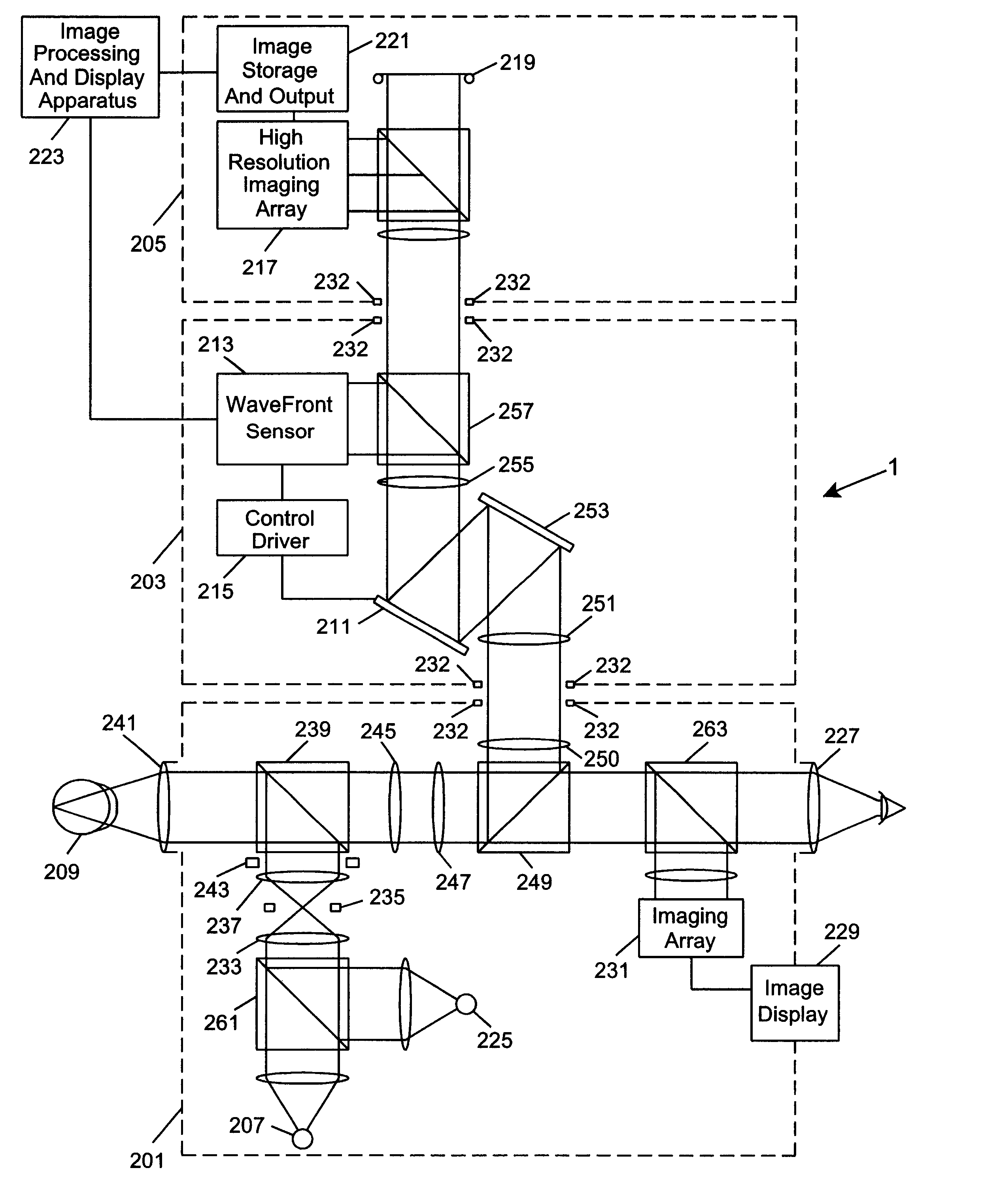
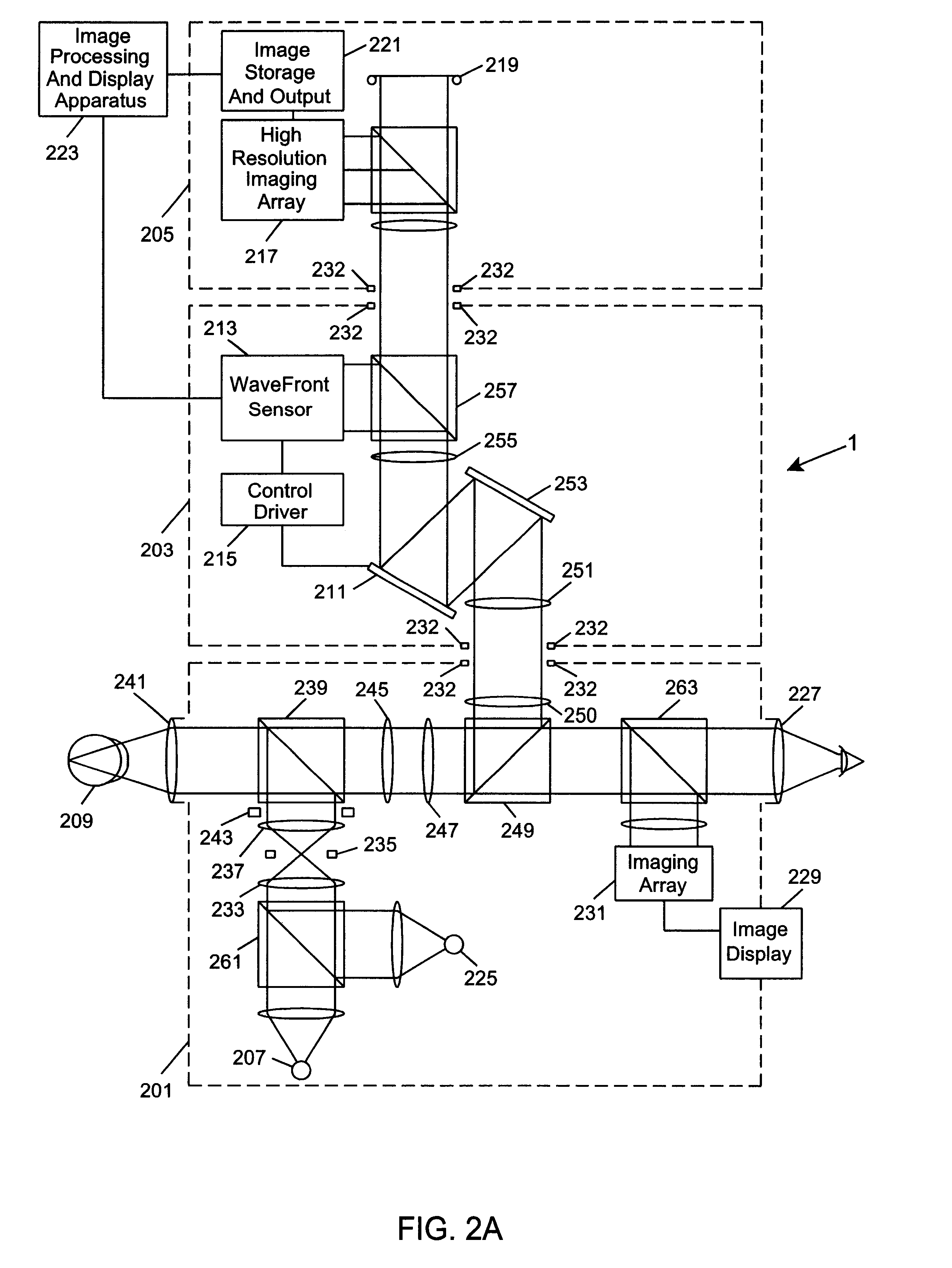
Referring to the figures in the accompanying Drawings, the preferred embodiments of the ophthalmic instruments of the present invention will be described in greater detail, wherein like elements will be indicated using like reference numerals.

According to the present invention, an ophthalmic imaging instrument includes a wavefront sensor-based adaptive optical subsystem that measures phase aberrations in reflections derived from light produced by an imaging light source and compensates for such phase aberrations when capturing images of reflections derived from light produced by the same imaging light source. For descriptive purposes, the wavefront sensor-based adaptive optical ophthalmic imaging instrument as described below comprises a fundus camera; however the present invention is not limited in this respect and is broadly applicable to any ophthalmic imaging instrument that captures images of the eye, including corneal topographer, retinal topographer, corneal imaging device, a...


PUM


Abstract

An improved ophthalmic instrument including an integral wavefront sensor and display device, wherein the wavefront sensor measures phase aberrations in reflections directed thereto to characterize aberrations of the eye and is operably coupled to the display device, which displays a graphical representation of the aberrations of the eye. Such graphical representation may include: two dimensional contour maps that graphically depict contribution of pre-specified terms (such as spherical aberration, astigmatism and coma) for the aberrations of the eye, coefficients corresponding to such pre-specified terms that characterize the aberrations of the eye, or predefined two-dimensional icons that provide a general graphical depiction of such prespecified terms. Such graphical representations provide the practitioner with valuable information characterizing the high order optical errors of the eye (which is far beyond the diopter information typically provided by current ophthalmic instruments) for use in diagnosis and treatment of abnormalities and disease in the eye.

Description

1. Field of the InventionThe present invention relates to ophthalmic instruments that aid in detection and diagnosis of eye disease, pre-surgery preparation and computer-assisted eye surgery (such as laser refractive surgery), including ophthalmic imaging and / or topography instruments (such as fundus cameras, corneal imaging devices, retinal imaging devices, corneal topographers, and retinal topographers) in addition to ophthalmic examination instruments (such as autorefractors, slit lamps and other indirect ophthalmoscopes).2. Summary of the Related ArtThe optical system of the human eye has provided man with the basic design specification for the camera. Light comes in through the cornea, pupil and lens at the front of the eye (as the lens of the camera lets light in). This light is then focused on the inside wall of the eye called the retina (as on the film in a camera). This image is detected by detectors that are distributed over the surface of the retina and sent to the brain ...

Claims


Application Information

Patent Timeline
Patent Type & Authority Patents(United States)
IPC IPC(8): A61B3/12A61B3/103A61B3/14A61F9/008A61F9/007
CPCA61F9/008A61F2009/00846A61F2009/00848A61F2009/00882A61F2009/00863A61F2009/00872A61F2009/00855A61B3/103
Inventor LEVINE, BRUCE MARTIN
Owner ADAPTIVE OPTICS ASSOC
Why Eureka
Try Eureka