Apparatus and method for wavelength selective switching
a wavelength selective switching and apparatus technology, applied in multiplex communication, instruments, optical elements, etc., can solve the problems of requiring apparatuses, which are relatively complicated, difficult and costly to realize, and may occur channel crosstalk problems, etc., to achieve the effect of significantly increasing the switching capacity
- Summary
- Abstract
- Description
- Claims
- Application Information
AI Technical Summary
Benefits of technology
Problems solved by technology
Method used
Image
Examples
first embodiment
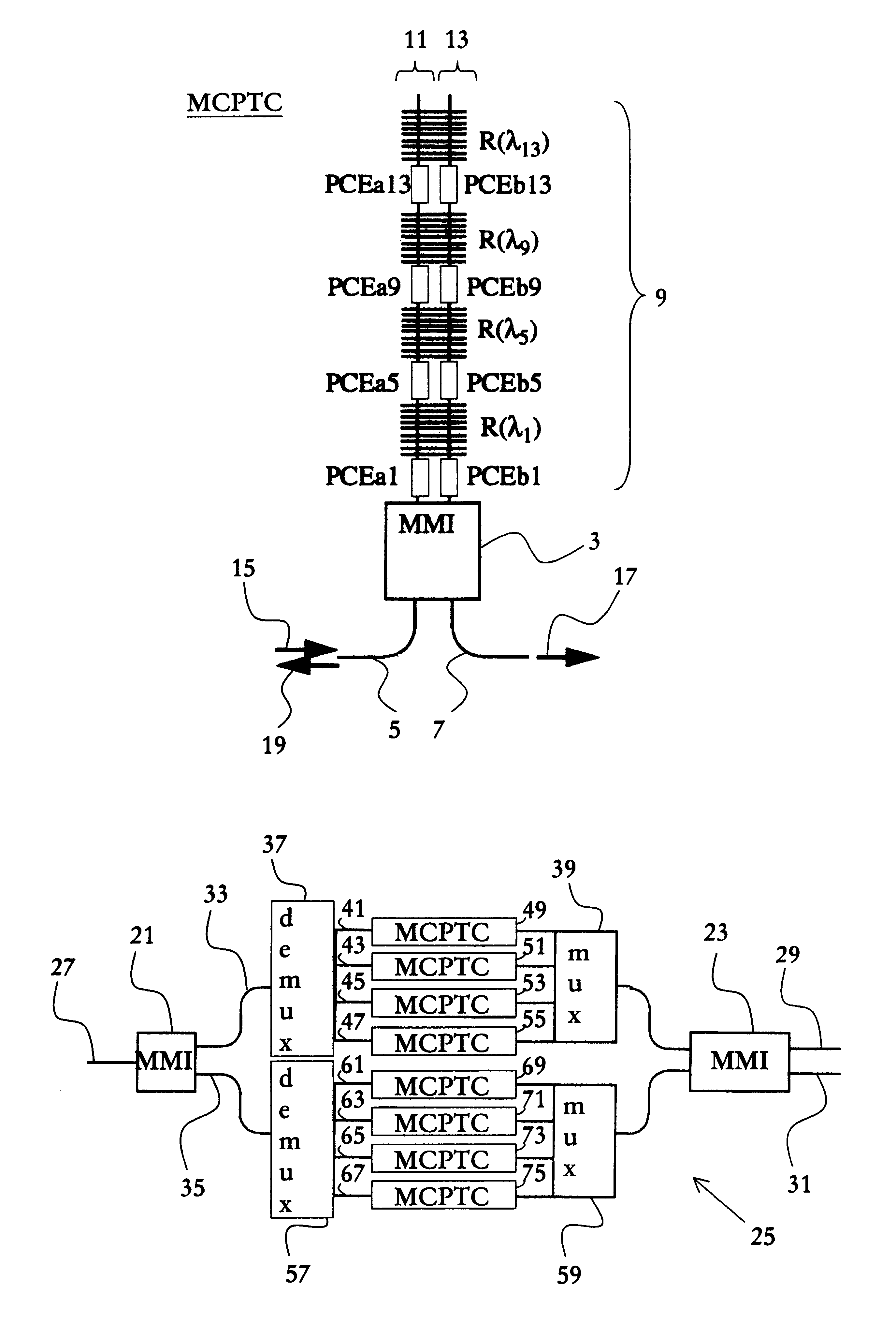
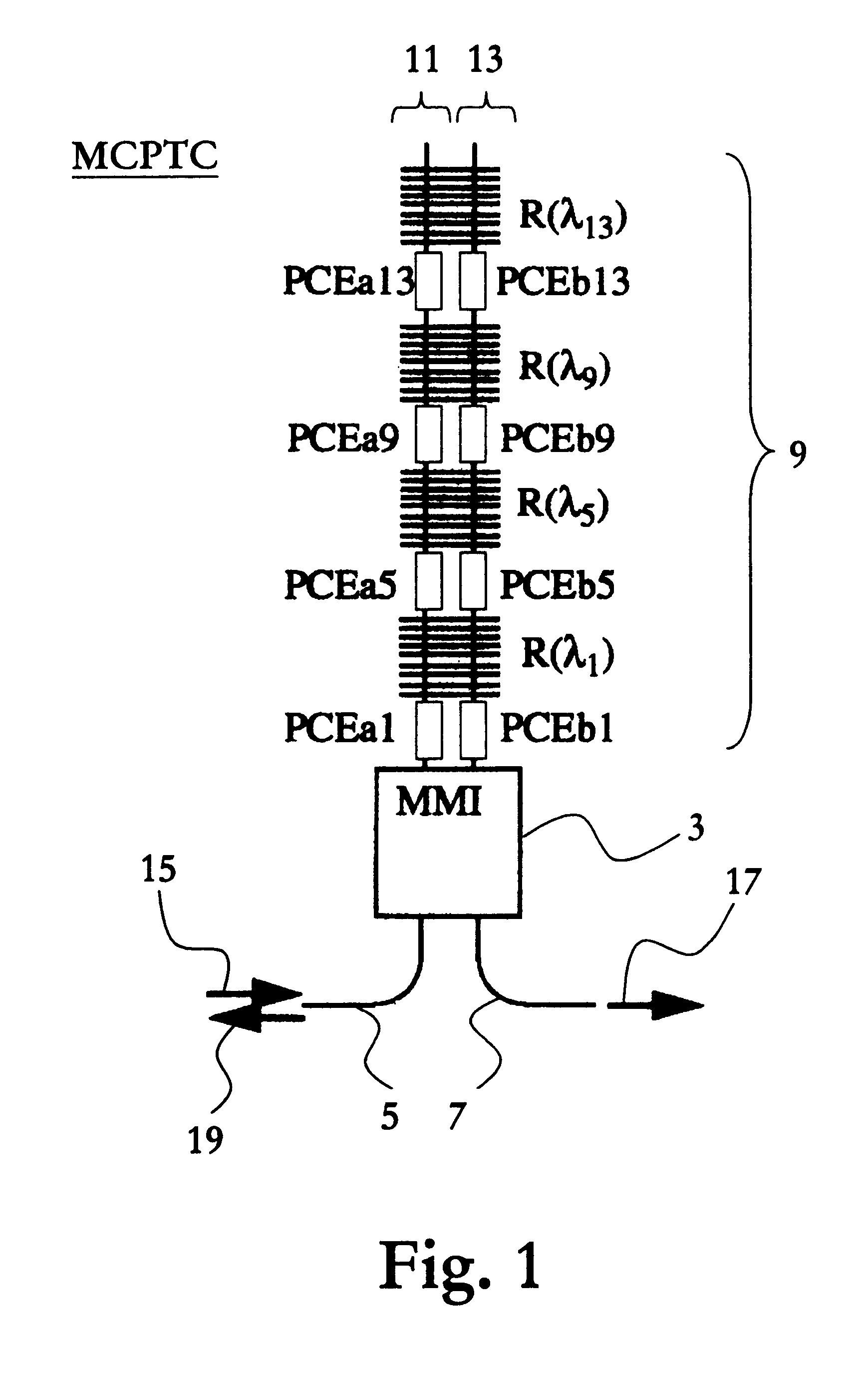
With reference next to FIG. 2, a 1.times.2 switch according to the present invention will be depicted. The switch comprises two MMI waveguides 21, 23 interconnected by a Mach-Zehnder waveguide 25. The MMI waveguide 21 has an input port, to which an access waveguide 27 is connected for input of a wavelength multiplexed optical signal comprising 16 channels, .lambda..sub.1, .lambda..sub.2, . . . , .lambda..sub.16. The MMI waveguide 23 has two output ports, to which a respective access waveguide 29, 31 is connected for output of two separated signals.
The Mach-Zehnder waveguide structure 25 comprises an upper arm 33 and a lower arm 35, which are arranged to transmit a respective portion of the intensity of the wavelength multiplexed optical signal.
The upper arm comprises a demultiplexing unit 37 and a multiplexing unit 39 interconnected by four waveguides 41, 43, 47, 49 arranged in parallel. The demultiplexing unit 37 and the multiplexing unit 39 are preferably MMIMZI-based devices, see...
third embodiment
With reference next to FIG. 5, a 4.times.4 switch according to the present invention will be depicted. The switch comprises two MMI waveguides 133, 134 interconnected by means of a Mach-Zehnder waveguide structure 136. The MMI waveguide 133 has four input ports 135, 137, 139, 141 for inputting of up to 4Q wavelengths channels .lambda..sub.1, .lambda..sub.2, . . . , .lambda..sub.4Q. The MMI waveguide 134 has four output ports 143, 145, 147, 149 for outputting of separated signals.
The Mach-Zehnder waveguide structure 136 comprises four arms 151, 153, 155, 157, which are each arranged to transmit a respective portion of the intensity of channels input into the switch.
Each of the four arms 151, 153, 155, 157 is provided with a respective multichannel wavelength selective phase control unit MCPTC2, as shown in FIG. 4, where each unit comprises 4Q Bragg gratings for handling of 4Q channels or channel groups.
Through active control of the phase control elements in the 4.times.4 switch shown...
fourth embodiment
With reference now to FIG. 7, a 2.times.2 switch according to the present invention will be described. The switch comprises two MMI waveguides 173, 174 interconnected by means of a Mach-Zehnder waveguide structure 176. The MMI waveguide 173 has two input ports 175, 177 for inputting of up to 32 wavelength channels .lambda..sub.1, .lambda..sub.2, . . . , .lambda..sub.32. The MMI waveguide 174 has two output ports 179, 181 for outputting of separated signals. The Mach-Zehnder waveguide structure 176 comprises two arms 182, 183, which each is arranged to transmit a respective portion of the intensity of input channels in the switch. Each of the arms 182, 183 is provided with two respective multichannel wavelength selective phase control units MCPTC3 of the type shown in FIG. 6 arranged in series.
The first multichannel wavelength selective phase control unit MCPTC3 in each arm, together denoted PC(.lambda..sub.1, .lambda..sub.2, . . . , .lambda..sub.16), is arranged for individual phase...
PUM
| Property | Measurement | Unit |
|---|---|---|
| optical wavelength | aaaaa | aaaaa |
| reflection | aaaaa | aaaaa |
| size | aaaaa | aaaaa |
Abstract
Description
Claims
Application Information
 - R&D
- Intellectual Property
- Life Sciences
- Materials
- Tech Scout
- Unparalleled Data Quality
- Higher Quality Content
- 60% Fewer Hallucinations
Browse by: Latest US Patents, China's latest patents, Technical Efficacy Thesaurus, Application Domain, Technology Topic, Popular Technical Reports.
© 2025 PatSnap. All rights reserved.Legal|Privacy policy|Modern Slavery Act Transparency Statement|Sitemap|About US| Contact US: help@patsnap.com


