Methods and apparatus for particle formation

a particle and particle technology, applied in the field of methods and apparatus for particle formation, can solve the problems of reduced product yield, problems such as problems, and processes such as seds are not suitable for all types of target substances, and achieve the effect of reducing the capacity of the target substance and high flow ra

Inactive Publication Date: 2003-06-10
NEKTAR THERAPEUTICS INC
View PDF3 Cites 39 Cited by
  • Summary
  • Abstract
  • Description
  • Claims
  • Application Information

AI Technical Summary

Benefits of technology

In the FIG. 2 system, the vehicle (in this example carbon dioxide) is fed from source 21 through cooler 22, pump 23 and heat exchanger 24, to bring it into a supercritical state. It is then fed into a mixing vessel 25, together with a solution of the target substance in an appropriate primary solvent (from source 26, via pump 27). The solution and the supercritical carbon dioxide enter the mixing vessel through a two-passage coaxial nozzle 28, of the type described above, which allows the kinetic energy of the carbon dioxide to act to disperse the solution, ensuring thorough mixing of the two fluids when they meet at the nozzle outlet. This yields a solution of the target substance in the carbon dioxide and the primary solvent, ie, effectively a solution of the target substance in modified supercritical carbon dioxide. The "modified" solution is maintained in a supercritical state by controlling the pressure and temperature inside the mixing vessel, using pressure regulator 29 and surrounding oven 30.
The supercritical solution then passes to a second nozzle 31, through which it is co-introduced into a particle formation vessel 32 with a second supercritical fluid flowing with a relatively high flow rate. Nozzle 31 is of the same general form as nozzle 28. At the same time, or substantially the same time, as the fluids meet and enter the vessel, the second supercritical fluid dissolves in the carbon dioxide vehicle, reduces its capacity for the target substance and thus causes precipitation of particles which can be collected in the particle retaining device 33. Again, supercritical conditions are maintained in the vessel 32 using back pressure regulator 34 and the oven 30.

Problems solved by technology

Processes such as SEDS are not however suitable for all types of target substance.
This can lead to reduced product yield, not to mention engineering problems when the solute later precipitates out of the supercritical fluid outside the particle formation vessel.
If the substance is at all soluble in the supercritical fluid, whether simply because of the chemical natures of the substance and the fluid (which may also contain modifiers), or because of the particular operating conditions (such as temperature and pressure) being used, problems can arise.
Such techniques are thus restricted in application to substances which are poorly soluble or completely insoluble in the chosen supercritical fluid.
For this particular supercritical fluid, it is generally non-polar or low polarity substances which cause problems, being either very or at least reasonably soluble in it.
Thus, for instance, low molecular weight lipophilic materials cannot easily be formed into particles using supercritical carbon dioxide.
In the past, such problems have been overcome either by altering the operating conditions to reduce solubility of the target substance in the supercritical fluid (it is not always possible, however, to alter the conditions sufficiently to achieve that), or by using a different technique altogether for particle formation.
However, RESS is generally a less accurate and reliable technique than techniques such as SEDS, allowing less control over the characteristics of the particles formed.
Alternatively, one might attempt to use a different supercritical fluid as the anti-solvent, but it can often be very difficult to select a supercritical fluid which is not only an anti-solvent for the target substance but also capable of dissolving the solvent vehicle--both requirements need to be met for the fluid to be useable.
Supercritical nitrogen, for instance, would act as an anti-solvent for the low molecular weight lipophilic materials which cannot be processed using supercritical carbon dioxide, but most conventional organic solvents are insoluble in supercritical nitrogen, so the choice of vehicle would be extremely limited.

Method used


Image

  • Methods and apparatus for particle formation
  • Methods and apparatus for particle formation
  • Methods and apparatus for particle formation

Examples


example 1a

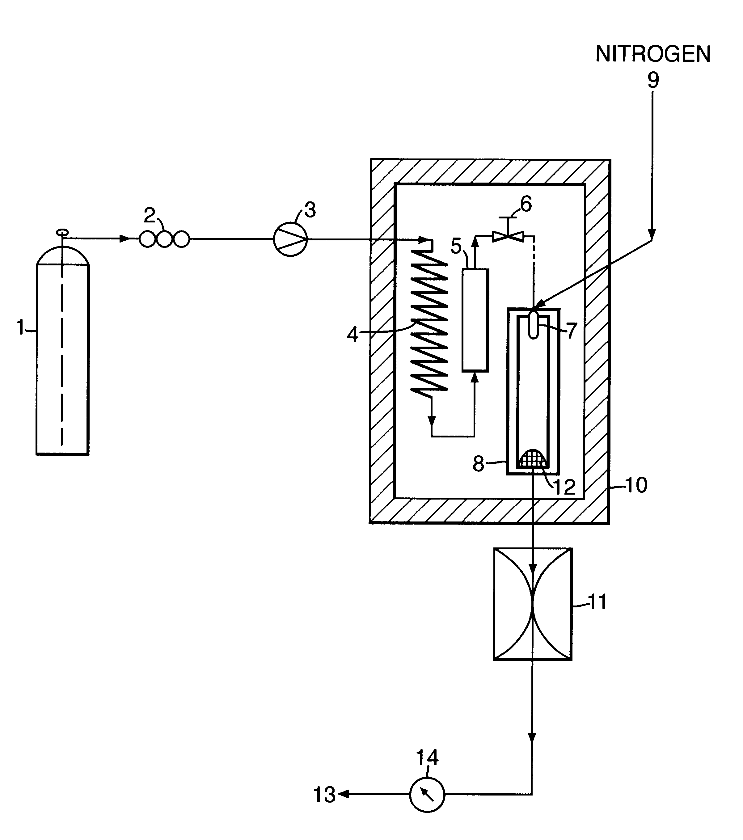
1g of ibuprofen was mixed with glass beads (200-300 micron, acid washed (Sigma, UK)) and introduced into a 10 ml Keystone vessel (the sample vessel 5) to form a uniform bed. The bed was sandwiched between two filters (average pore size 2 microns) to eliminate the risk of physical entrainment of drug particles in the carbon dioxide flow. The sample vessel was provided with a pressure regulator independent of that of the particle formation vessel 8.

The fluids were introduced into the particle formation vessel using a two-passage coaxial nozzle of the preferred type described above, having a 0.1 mm diameter outlet. The nozzle ensured thorough mixing of the fluids at their point of contact, ie, at their point of entry into the vessel. The conditions in the vessel were such that particle formation occurred simultaneously, or substantially so, on the fluids meeting and entering the vessel.

1 ml / min of carbon dioxide (measured at the pump head) was pumped into the sample vessel containing t...

example 1b

Example 1a was repeated, but with the carbon dioxide flow rate increased from 1 to 4 ml / min (at the pump head). All other operating conditions remained the same.

The product was a fine fluffy white powder. Analysis using the Aerosizer / Aerodisperser system yielded the particle size distribution curve shown in FIG. 4 and summarised in Table 2. The mean particle diameter, by volume, was about 14 micron.

example 1c

Again Example 1a was repeated, but this time with a carbon dioxide flow rate of 8 ml / min (at the pump head). The product was again a fine fluffy white powder, which when analysed (see FIG. 5 and Table 3) showed a mean particle diameter, by volume, of about 8 micron.


PUM

PropertyMeasurementUnit
diameteraaaaaaaaaa
diameteraaaaaaaaaa
diameteraaaaaaaaaa

Abstract

The invention provides a method for forming particles of a target substance (26), involving: (a) preparing a solution or suspension of the substance in a vehicle (21) which is or includes either a near-critical fluid (21) or a first supercritical fluid; (b) introducing the solution or suspension into a particle formation vessel (32); and (c) contacting the solution or suspension, in the particle formation vessel, with a second super-critical fluid, under conditions which allow the second supercritical fluid to cause precipitation of particles of the target substance from the solution or suspension; wherein the second supercritical fluid is miscible or substantially miscible with the vehicle and is a fluid in which the target substance is insoluble or substantially insoluble. Also provided is apparatus for use in carrying out an embodiment of the method, including a particle formation vessel and means for controlling the temperature and pressure inside it; a fluid mixing vessel and means for controlling the temperature and pressure inside it; first fluid inlet means for introducing into the fluid mixing vessel a vehicle and a solution of a target substance in a primary solvent, so as to form in the fluid mixing vessel a solution of the substance and the primary solvent in the vehicle; and second fluid inlet means for introducing the solution thus formed, preferably together with a second supercritical fluid, into the particle formation vessel. The invention also provides a particulate product formed using the method.

Description

This invention relates to the controlled formation of particulate products using supercritical fluids. It provides methods and apparatus for the formation of substances in particulate form, and also particulate products of the methods.BACKGROUND TO THE INVENTIONIt is known to form particles of a substance of interest (a "target substance") by dissolving or suspending it in a suitable vehicle and then using a supercritical fluid anti-solvent to extract the vehicle to cause particle precipitation.One particular technique for doing this is known as "SEDS" (Solution Enhanced Dispersion by Supercritical fluids). This is described in WO-95 / 01221 and (in a modified form) in WO-96 / 00610. The essence of SEDS is that a solution or suspension of a target substance, in an appropriate vehicle, is co-introduced into a particle formation vessel with a supercritical fluid anti-solvent having a relatively high flow rate, in such a way that two things happen substantially simultaneously and substanti...

Claims


Application Information

Patent Timeline
Patent Type & Authority Patents(United States)
IPC IPC(8): A61K9/16B01J2/02B01J2/04B01J3/00A61K9/14B01J19/00
CPCA61K9/1688B01J2/04B01D11/0407B01J3/008B01D11/0403B01D11/0488Y02P20/54
Inventor HANNA, MAZEN HERMIZYORK, PETER
Owner NEKTAR THERAPEUTICS INC
Why Eureka
Try Eureka