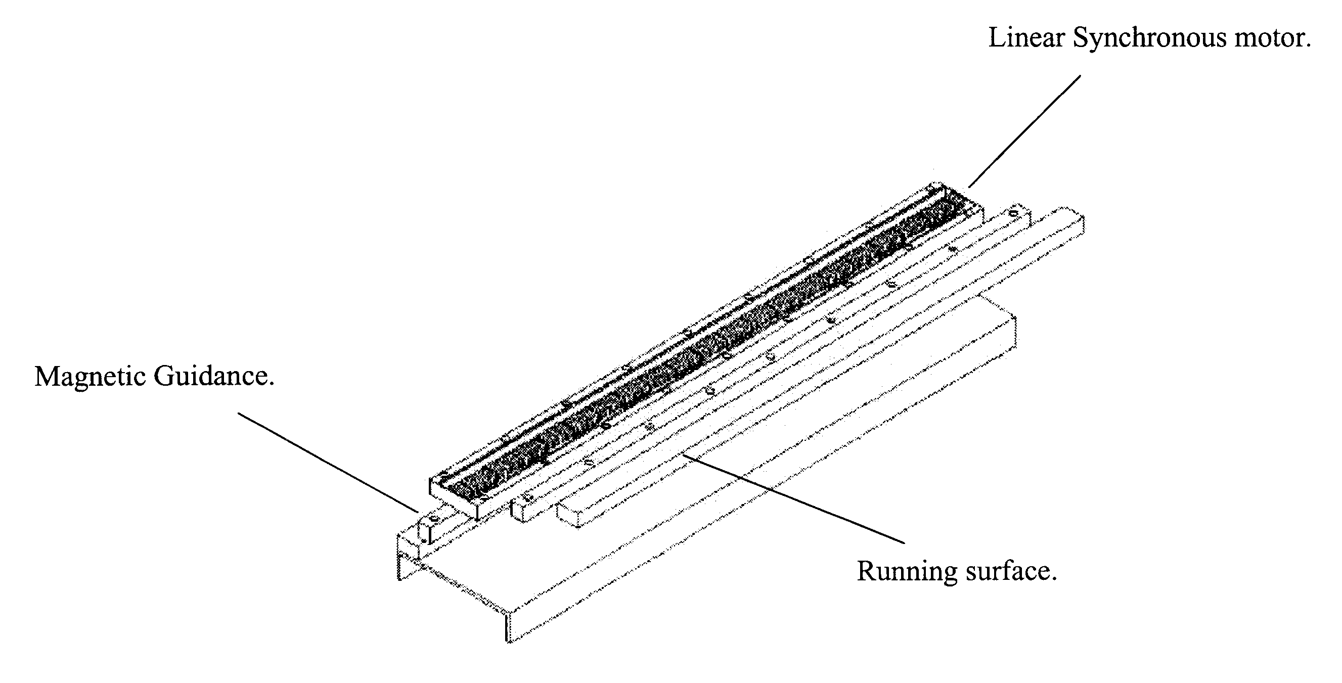
One aspect of the invention integrates a combination of one or more subcomponents for linear motor propulsion,
vehicle guidance, position sensing, communication, and vehicle or pallet running surfaces during the manufacturing of the guideway module. A single manufacturing operation can be used to position,
affix, and encapsulate the selected subcomponent(s) in a module or modules. For example, the component(s) can be designed to be located in a plastic injection mold, typically, a reaction injection mold (RIM), which allows the subcomponent(s) to be positioned, aligned, and encapsulated in a single manufacturing step that has only a several minute
cycle time. In this manner positional accuracy among the relationship of the subcomponent(s) can be maintained within a small tolerance (on the order of 0.25 mm) while costs remain very low.
Subcomponents are designed for integration into the guideway, either as a single encapsulated module or as separate but integrated units, thereby reducing the need to manufacture and ship many individual parts, fixtures, and fasteners to the site where the transport system is being installed. For example, the motor
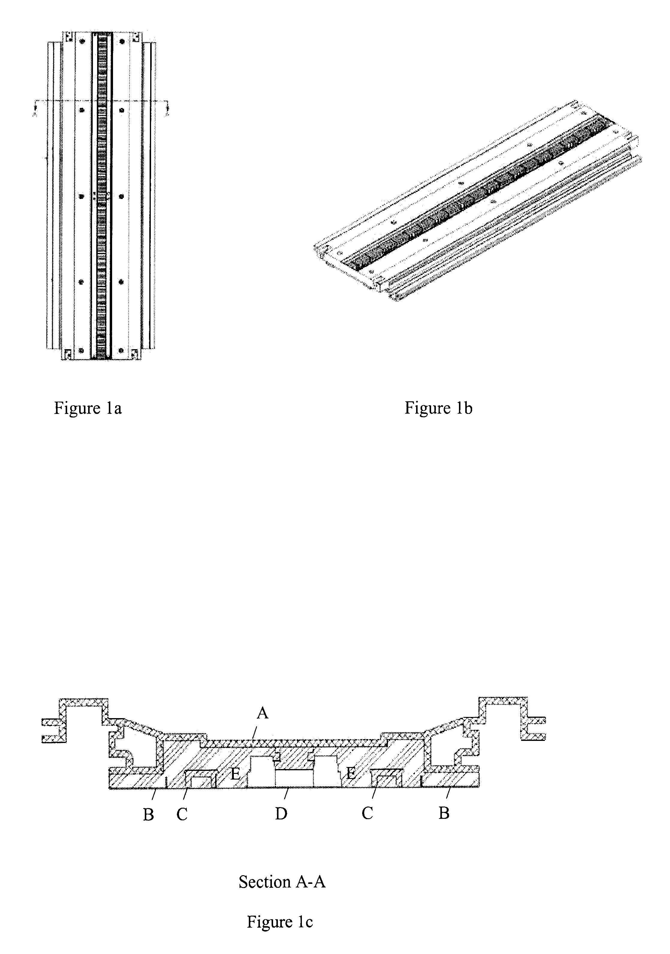
stator iron is segmented into blocks for use in both straight and curved modules. These
stator iron blocks
mount to a backplate for support and preliminary alignment during manufacturing. In a process such as RIM, the mold, as it closes, precisely aligns the
stator iron blocks using features designed into the surface of the stator iron blocks. Where subcomponents are encapsulated as a single unit, the use of a backplate can have other integrated features as well. For example, it can provide support for the guidance channels prior to encapsulating the guideway module. It can also provide strength for the subcomponents during the encapsulating process so that the parts do not have to be designed as precision stand-alone components, thus reducing the cost of the subcomponents.
In a
modular design of the guideway, a single manufacturing process such as encapsulating the components in a molding process allows for minimal treatment of surface finishes of the parts. For example, a molding material such as urethane, or
epoxy fills the space between the components, forming the guideway. This encapsulates the components. Material that is injection molded around the component s will take the shape of the component, even if it is irregular. Once molded, the parts are scaled from the environment so that painting and plating are not necessary. This lowers the cost of the system and reduces the need for special handling of parts. Manufacturing motor subcomponents in this manner also provides the parts with a tolerance accuracy from the molding process that is suitable for installation registration without the need for additional surface
machining or other expensive finishing of subcomponent surfaces.
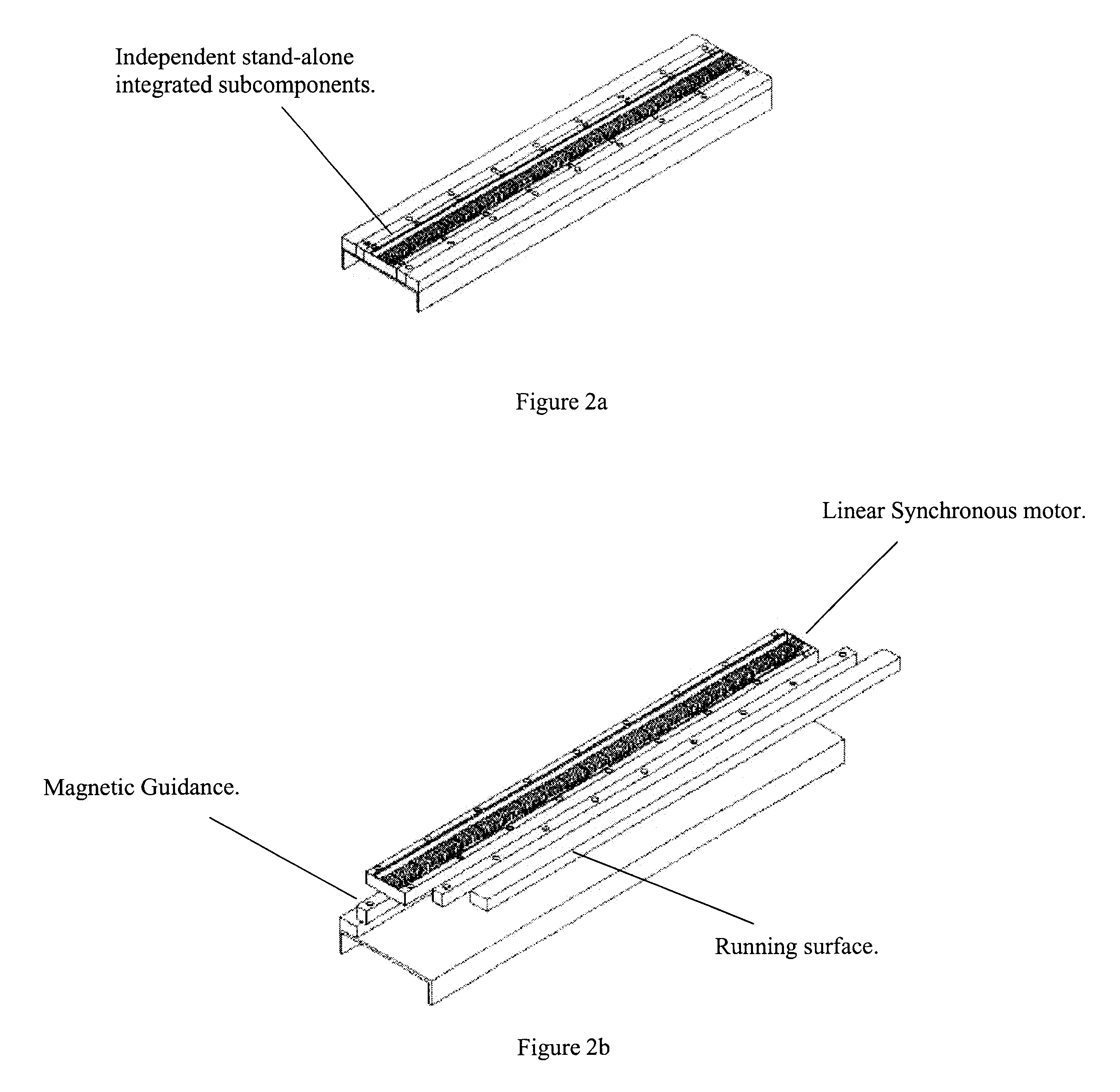
Another aspect of the invention is the
product design methodology that allows for the transport system to also be manufactured as independent subcomponents that can be installed with no adjustment unlike such current systems as belt driven transport or pallet systems. For example, if an existing transport system already has a method of position sensing, then just the linear motor propulsion subcomponent can be manufactured and used as a replacement for the inadequate existing propulsion method. Using similar manufacturing techniques as the modular guideway, the stand-alone individual subcomponent has a low cost mechanical packaging that incorporates manufacturing efficiencies such as, built in features of highly repeatable dimensional tolerances, integrated mounting features possibly molded during a RIM process, and little or no secondary
surface finish operations.
Another aspect of the invention is the improvement of the efficiency of the manufacturing process and of the resulting module by integrating the functions of the parts. For example, in mounting the stator iron to the backplate, if the contact area between the two parts is great enough and can be maintained during the manufacturing process, then the backplate will function as a
heat sink for the linear motor propulsion. Dissipating heat in this manner increases
motor efficiency and eliminates the need for additional
heat sink parts and
assembly. Using an encapsulating material such as urethane in a molding operation to bond the subcomponents together allows the module be very rigid, drawing from the strength of the encapsulant, the guidance components, and the backplate. The components function as a single
composite structure. Another integration
advantage is that the components can have a common ground for static dissipation. Transportation vehicles and pallets moving over the guideway module surface will tend to build up a static charge due to the vehicular or pallet motion. The running surfaces, for example, could be electrically bonded to other components or directly to a backplate, which in turn, could be connected to a common grounding
bus for the transportation system. In this way, the vehicle or pallet can be prevented from building a static charge that could cause damage to cargo or other
peripheral devices.
Subcomponents for the switch are similar to other guideway modules, however there are also unique subcomponents that that facilitate the vehicle or pallet to move from one path to another. These subcomponents are integrated during the time of manufacturing. For example, using linear motor propulsion with any combination of one or more subcomponents, active guidance and
power switching electronics can be encapsulated in the guideway module. This type of switch eliminates
moving parts. It also simplifies the switch installation, and lowers the cost of the system. Integrating these specialized components into the guideway module reduces installation setup, training, maintenance, and complexity.

