Reciprocating compressor

a compressor and reciprocating technology, applied in the direction of machines/engines, liquid fuel engines, positive displacement liquid engines, etc., can solve the problems of increasing the space where the compressor is located, increasing the electric consumption of the electric drive portion and a high cast, and achieving the effect of decreasing the pulsation

Inactive Publication Date: 2003-07-08
SANYO ELECTRIC CO LTD
View PDF9 Cites 24 Cited by
  • Summary
  • Abstract
  • Description
  • Claims
  • Application Information

AI Technical Summary

Benefits of technology

It is the fourth object of the present invention to provide the reciprocating compressor of the type improved in decreasing the

Problems solved by technology

To correspond with these requirement, the inner volume thereof can be increased by providing a large diameter of the cylinder and the piston of the compression means, however it will cause a large sizing of the compressor, an increase of electric consumption of the electric drive portion and a high cast.
Further to use a plurality of compressors will cause an increase of space where compressors are located and an increase of the cost and the like.
However it is necessary to cut and remove a part of t

Method used


Image

  • Reciprocating compressor
  • Reciprocating compressor
  • Reciprocating compressor

Examples


embodiment 1

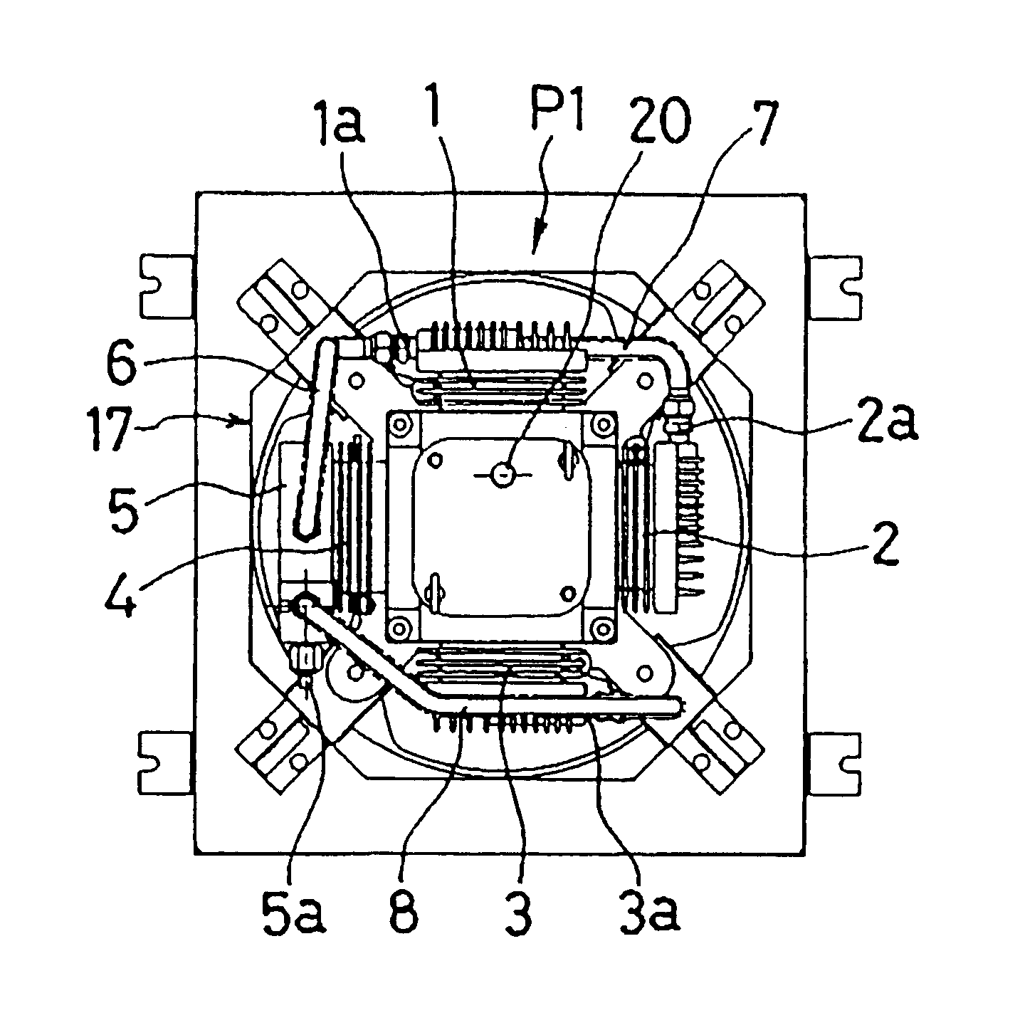
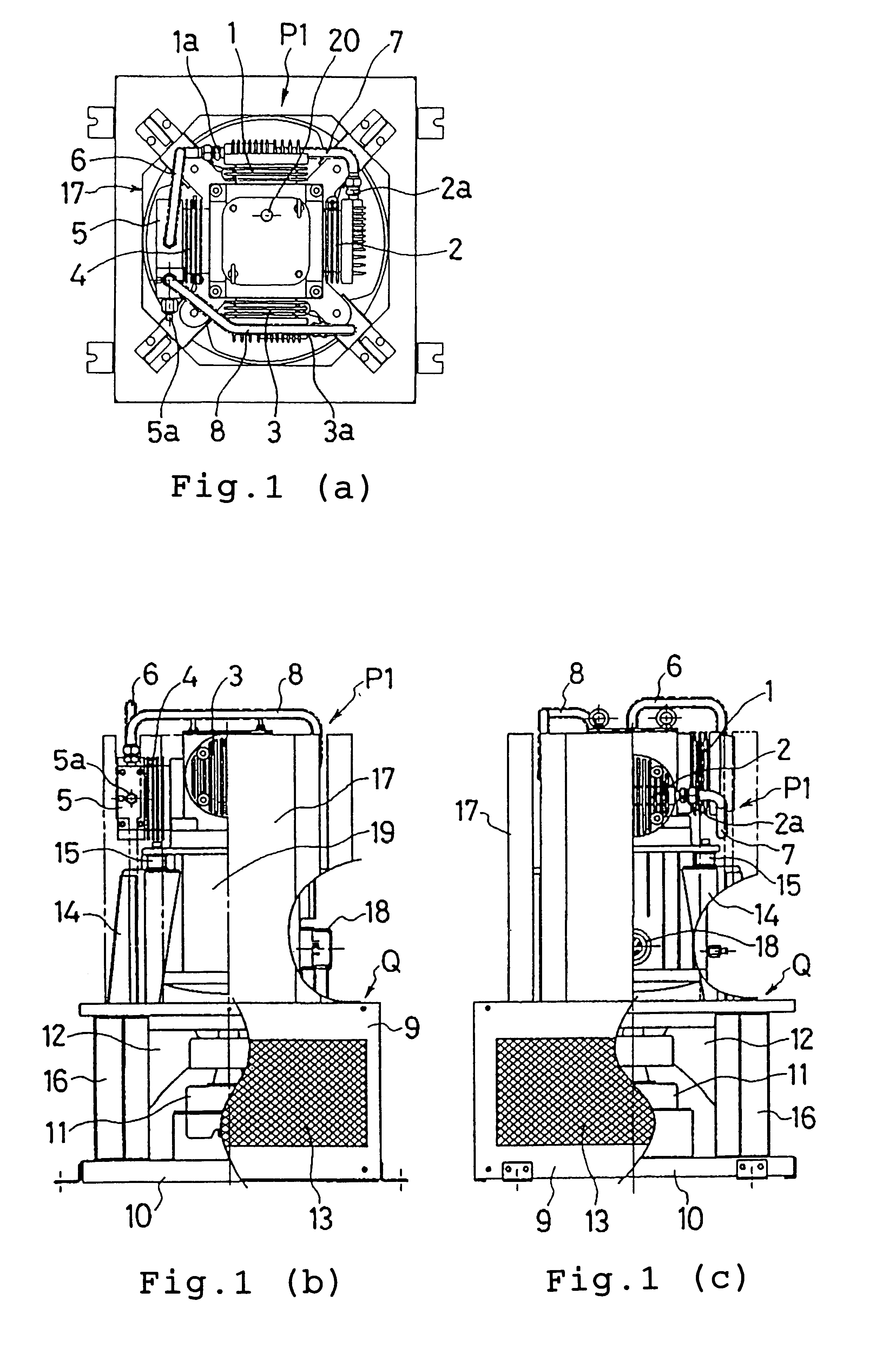
It is an embodiment to achieve the first object of the present invention in, FIG. 1(a) illustrates a general of the reciprocating compressor by respective plane view, (b) is partially cut-away front view and (c) is partially cut-away side view. In a reciprocating compressor P1, four gas compressors that is, the first gas compression means 1, the second one 2, the third one 3 and the fourth one 4 are oppositely disposed one another in a cross shape. These four gas compression means 1 to 4 respectively include cylinders and pistons. These are different from the conventional reciprocating compressor described hereinbefore and these have one another the same inner volume and the same compressing performance. The piston of the first gas compression means 1 and the piston of the third gas compression means 3 are connected on the same axis with each other to one of yokes and the piston of the second gas compression means 2 and the piston of the fourth gas compression means 4 are connected ...

embodiment 2

The second object of the present invention can be achieved by this embodiment, in FIG. 4, numeral 121 illustrates a discharge block which is mounted on a discharge port 5a of the cylinder head 5 in the fourth gas compression means 4 by a fastening bolt 122. An expansion muffler 123 is formed at the joining portion for the discharge port 5a of the discharge block 121. The expansion muffler 123 is formed by providing a space portion S having a larger inner diameter than that of the discharge port 5a of the cylinder head 5 and a discharge opening 124 having a smaller inner diameter than that of the space portion S is formed at the end of the muffler 123. A gas supply tube (not shown) is connected to the discharge opening 124.

As described hereinbefore, gases compressed by the first gas compression means 1 to the third gas compression means 3 are respectively fed into the cylinder head 5 at the side of the fourth gas compression means 4 through the first connecting tube 1 to the third co...

embodiment 3

The embodiment refers to achieve the third object of the present invention, in FIG. 5, numeral 221 illustrates a flywheel of which upper end portion is provided with a cylindrical attachment portion 221a and of which axial direction is provided with an attachment hole 221b. The cylindrical attachment portion 221a is formed on a base of a shaft hole 222a of a rotor 222 in the electric motor part 19, that is, an outer diameter of the attachment portion 221a is designed to correspond with an inner diameter of the shaft hole 222a of the rotor 222. For attaching the flywheel 221, the cylindrical attachment 221a is inserted into the shaft hole 222a of the rotor 222 so as to contact its upper end surface with the lower end surface of the crankshaft 223 and a fastening bolt 224 is inserted into the attachment hole 221b to be threaded and fastened in a screw hole 223a which is provided in an axial direction of the crankshaft 223.

At the time of attaching the flywheel on the crankshaft, an axi...


PUM


Abstract

A reciprocating compressor provided with a plurality of gas compression means having a cylinder and a piston, the piston of each gas compression means is cooperated with the, compressor by converting a rotating motion of a crankshaft provided on an electric drive source to a reciprocating motion by a scotch yoke mechanism, wherein an increase of the volume of discharged gas can be achieved without designing a gas compression means to be wide or without increasing the number thereof, a pulsation of discharged gas can be decreased by an attachment of an expression muffler on the cylinder head so as to decrease a vibration and noise of the compressor, an attachment of the fly wheel to the crankshaft and an adjustment of the shaft with the crankshaft can be improved easily, further compressed gas flows are joined and discharged in concentration, thereby the pulsation of discharged gas can be restrained.

Description

BACKGROUND OF THE INVENTION1. Field of the InventionThe present invention relates to a reciprocating compressor in which a plurality of gas compression means having a cylinder and a piston is provided, the pistons of each gas compression means are formed to cooperate by converting a rotating motion of a crankshaft provided on a driving source to a reciprocating motion.2. Detailed Description of the Prior ArtIn a normal reciprocating compressor, one gas compression means having a cylinder and a piston is provided, while there has been a reciprocating compressor having a plurality of gas compression means conventionally. In such reciprocating compressor having a plurality of gas compression means, for embodiment as shown by FIG. 9(a), three gas compression means 101, 102, 103 having the cylinders and the pistons are oppositely arranged to achieve a reciprocating motion of the piston on orthogonal axis 105, 106, it is known that gas is compressed and high-pressurized from the gas compr...

Claims


Application Information

Patent Timeline
IPC IPC(8): F04B39/00F04B25/00F04B53/00
CPCF04B25/00F04B39/0055F04B53/00
Inventor NISHIKAWA, TAKAHIRONISHIKAWA, HIROSHIHARAKO, TAKASHIMIZUNO, TAKAYUKISATO, KAZUYASAKAMOTO, YASUO
Owner SANYO ELECTRIC CO LTD
Why Eureka
Try Eureka