System and method for performing timing analysis, including error diagnosis, signal tracking and clock skew

Inactive Publication Date: 2003-07-15
NEC CORP
View PDF1 Cites 37 Cited by
  • Summary
  • Abstract
  • Description
  • Claims
  • Application Information

AI Technical Summary

Benefits of technology

It is a still further object of the invention to increase circuit design flexibility by taking advantage of events which occur within a certain time period of one another, due to environmental parameters of the circuit such as process, voltage and/or temperature variations. The invention accomplishes this object by design

Problems solved by technology

One of the shortcomings of currently available commercial tools is that they either do not deal with guarantees and requirements, or, if they do, the results are frequently incorrect or unreliable.
This limits the application of these tools for describing timing guarantees, signal tracking and clock jitter, all of which require linear constraints as well as max constraints.
Also, the inability to use linear constr

Method used


Image

  • System and method for performing timing analysis, including error diagnosis, signal tracking and clock skew
  • System and method for performing timing analysis, including error diagnosis, signal tracking and clock skew
  • System and method for performing timing analysis, including error diagnosis, signal tracking and clock skew

Examples


Embodiment Construction

Error diagnosis will be illustrated using a cache read hit bus cycle for an Intel 80386 system. The hardware configuration used in the example is shown in FIG. 6. The 386 microprocessor issues a read request which is routed to the cache controller (32385). The cache controller determines that the data value needed is currently in the cache and enables the transparent latch (74 FCT 373 T) to pass the address to the cache SRAM (2147H-2). Also enabled is a transceiver (74 FTB 245 A) at the output of the SRAM which then makes the data value available on the 386 local data bus for the microprocessor to read at its data ports.

Using the data sheets for the parts specified above, a timing diagram shown in FIG. 7 was created. On the top line of the figure, a violated min bound setup time 386_t21 (between the D0-D31 data inputs of the microprocessor and the microprocessor clock) is shown. The lower and upper bounds of some relevant constraints in this example are given in Table 1. The setup t...


PUM


Abstract

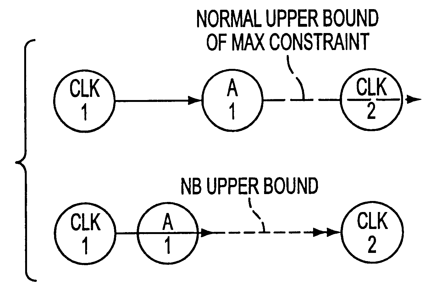
A method for performing timing analysis comprising inputting circuit timing information for a circuit, including temporal constraints between events of a desired circuit operation. A timing diagram representing the desired circuit operation, based on the circuit timing information is generater. All violated constraints within said timing diagram are identified. The method forces no violations of said violated constraints by designating the violated constraints as Non-Breakable (NB) constraints, such that a time difference from a source event to a destination event which defines said NB constraint is no less than a minimum bound and no more than a maximum bound of a linear constraint representing a timing requirement between the source and the destination events.

Description

I. BACKGROUND OF THE INVENTION1. Field of the InventionThe automation of interface timing verification is important for the design of reliable systems composed of several interconnected components. Due to manufacturing or environmental variation, the delay between two signal transitions of a component may not be a precise number, and is usually specified with a lower bound and an upper bound by the manufacturers. Exhaustive simulation, where all possible combinations of delay values are checked, is impractical for large systems. Therefore, efficient analytical verification algorithms are necessary to ensure that all timing requirements will be satisfied for all possible delay values.2. Description of the Related ArtA convenient means for describing the timing interaction of signals and events is a timing diagram. A timing diagram is a set of signals, where each signal is composed of signal edges which represent events in time such as a transition from high to low, transition from hi...

Claims


Application Information

Patent Timeline
IPC IPC(8): G06F17/50
CPCG06F17/5031G06F30/3312
Inventor CASAVANT, ALBERT E.
Owner NEC CORP
Why Eureka
Try Eureka