Exposure apparatus, a photolithography method, and a device manufactured by the same

a technology of photolithography and exposure apparatus, which is applied in the direction of microlithography exposure apparatus, printers, instruments, etc., can solve the problems of image warpage, reduced glass material transmission factor, and limited availability of glass material that can be used to secure a high transmission factor

Inactive Publication Date: 2003-07-29
NIKON CORP
View PDF14 Cites 36 Cited by
  • Summary
  • Abstract
  • Description
  • Claims
  • Application Information

AI Technical Summary

Problems solved by technology

In addition to that caused by distortion, which originates in the projection optical system, there is image warping that is caused by the bend of the wafer that is printed by the image side of the projection optical system as well as that caused by the bend of the reticle drawn by the circuit pattern on the object side of the projection optical system.
In order to improve the resolving power, the problem lies in the reduction of the transmission factor of the glass material constitutes the projection optical system when using an exposure light with a short wavelength, and in the limited availability of glass material that can be used to secure a high transmission factor.
Rather, because a portion of the lost light is absorbed into the glass material and through its conversion to heat energy, the refractive index of the glass material of the lens changes or the shape of the lens surface changes, thereby resulting in a reduction of the performance of image formation and especially causing fluctuation in the aberration in the exposure.
On the other hand, the use of a glass material having a refractive index that exceeds the upper limit value of conditional expression (2) as the lens having exposure light with a high energy density which satisfies conditional expression (1), is not favorable because it leads to the reduction of the image formation performance, which occurs due to the reduction in the transmission factor.
Conversely, by providing a lens that does not completely satisfy conditional expression (4) but is comparatively low in energy density of the exposure light that satisfies conditional expression (3), the refractive power in the entire projection optical system is unable to be increased, which leads to unfavorable elongation of the projection optical system.
When exceeding the upper limit value of conditional expression (6), the positive distortion generated by the first lens group becomes less able to correct the negative distortion generated by the second, fourth and fifth lens groups and is therefore unfavorable.
When falling below the lower limit value of the conditional expression (6), this becomes the cause of the generated higher order positive distortion and is therefore not favorable.
When exceeding the upper limit value of conditional expression (7), the correction of the Petzval sum becomes insufficient and it becomes more difficult to achieve the flattening of the image plane.
Therefore, exce

Method used


Image

  • Exposure apparatus, a photolithography method, and a device manufactured by the same
  • Exposure apparatus, a photolithography method, and a device manufactured by the same
  • Exposure apparatus, a photolithography method, and a device manufactured by the same

Examples


first embodiment

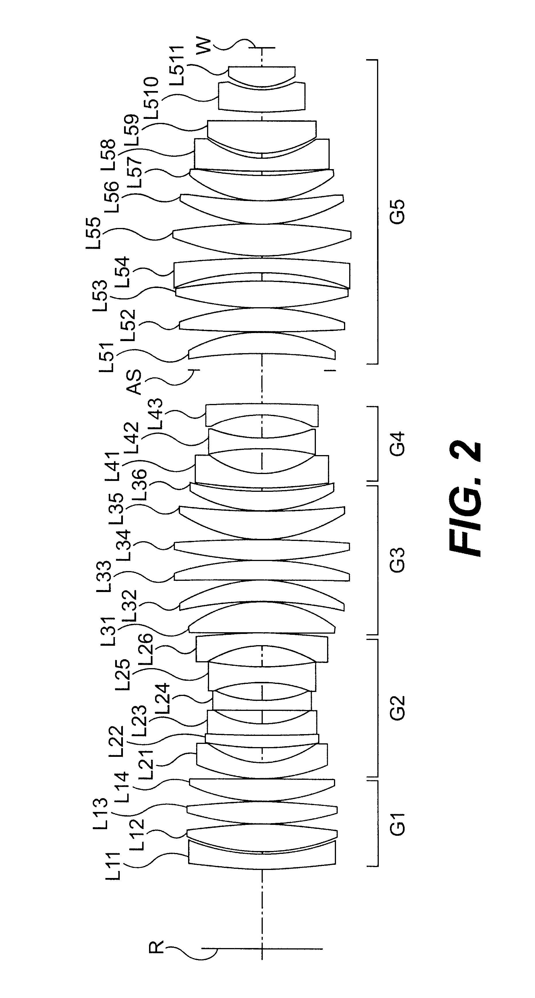
FIG. 2 is a drawing that shows the lens construction of the projection optical system that relates to the This embodiment has, relative to the reticle R (object plane) as the first object, a first lens group G1 having a positive refractive power and with at least one negative lens L11; and a second lens group G2 having a negative refractive power; and a third lens group G3 having a positive refractive power; and a fourth lens group G4 having a negative refractive power; and a fifth lens group G5 having a positive refractive power with at least two negative lenses L54 and L58. Furthermore, it is both-sidedly telecentric on the wafer W (image plane) side for the second object and the reticle R (object plane) side.

Further, with the fifth lens group described above of the projection optical system of FIG. 2, the lens L59, L510, L511 are comprised so as to satisfy the conditional expressions (1) and (2). In this manner, a higher transmission factor can be secured in a lens with a high e...

embodiment example 2

II. Preferred Embodiment Example 2

FIG. 5 is a drawing that shows the lens construction of the projection optical system that relates to the second embodiment. It has, in order from the reticle R (object plane) as the first object, a first lens group G1 having a positive refractive power and with at least one negative lens L11; and a second lens group G2 having a negative refractive power; and a third lens group G3 having a positive refractive power; and a fourth lens group G4 having a negative refractive power; and a fifth lens group G5 having a positive refractive power with at least two negative lenses L54 and L58. Furthermore, it is both-sidedly telecentric on the wafer W (image plane) side for the second object and the reticle R (object plane) side.

Further, the lens L59, L510, L511 are comprised so as to satisfy the conditional expressions (1) and (2). In this manner, a higher transmission factor can be secured in a lens with a high energy density of the exposure light thereby m...

embodiment example 3

III. Preferred Embodiment Example 3

FIG. 8 shows the lens construction of the projection optical system that relates to a third embodiment of the present invention. It has, in order from the reticle R (object plane) as the first object, a first lens group G1 having a positive refractive power and with at least one negative lens L11; and a second lens group G2 having a negative refractive power; and a third lens group G3 having a positive refractive power; and a fourth lens group G4 having a negative refractive power; and a fifth lens group G5 having a positive refractive power with at least two negative lenses L54 and L58. Furthermore, it is both-sidedly telecentric on the wafer W (image plane) side for the second object and the reticle R (object plane) side.

Further, the lens L59, L510, L511 is comprised so as to satisfy the conditional expressions (1) and (2). In this manner, a higher transmission factor can be secured in a lens with a high energy density of the exposure light there...


PUM


Abstract

The present invention is directed to a batch type projection exposure apparatus for being used with a scanning type exposure apparatus. The apparatus may include an illumination optical system and a projection optical system. The illumination optical system may have a light source that illuminates a mask with an exposure light from the light source, and the projection optical system may have an image field that projects a reduction image of a pattern on the mask onto the image field on a work piece. The image field may include a rectangular shaped pattern transfer area of the scanning type exposure apparatus. The projection optical system may also have a numerical aperture at the side of the work piece that is greater than or equal to 0.5 m, and a rectangular pattern transfer area which is same as the rectangular shaped pattern transfer area of the scanning type exposure apparatus. The rectangular pattern transfer area of the projection optical system may be encompassed within the image field on the projection optical system.

Description

1. Field of the InventionThe present invention relates to a manufacturing method of a device (such as a semiconductor elemental device, photo-imaging elemental device, flat panel display device such as a LCD (liquid crystal display) element device, a PDP (plasma display panel) element device, EL (electroluminescent) display element device, FED (field emission display) element device, Electric Paper display element device etc., thin film magnetic head elemental device, and so forth) that uses a projection exposure apparatus at the time of photo-transferring a mask pattern onto a substrate within the process of lithography for manufacturing the device, wherein the projection optical system for projecting the image of the pattern of the first object onto the second object and the projection optical system thereof are provided.2. Description of the Related ArtWhen manufacturing a semiconductor elemental device or so forth, a projection exposure apparatus in a scanning exposure format is...

Claims


Application Information

Patent Timeline
IPC IPC(8): G02B13/14G03F7/20
CPCG02B13/146G03F7/70241
Inventor SHIGEMATSU, KOJI
Owner NIKON CORP
Why Eureka
Try Eureka