
Ceramic shell thermal spray powders and methods of use thereof

a technology of thermal spray powder and ceramic shell, which is applied in the field of substrate coating process, can solve the problems of large difficulty in source of imperfections in the coating, and increase the difficulty of controlling the temperature of the flame and the rate of injection, so as to achieve greater conformability to the substrate and the effect of coating thickening

Inactive Publication Date: 2003-08-05
SAINT GOBAIN ABRASIVES INC
View PDF3 Cites 4 Cited by
  • Summary
  • Abstract
  • Description
  • Claims
  • Application Information

AI Technical Summary

Benefits of technology

The composite particles obtained can be used to coat a substrate allowing a much greater thickness of coating to be obtained and, if the nature of the combustible material is chosen appropriately, a coating with much greater conformability to the substrate and therefore a much reduced danger of a coating subject to spalling.

Problems solved by technology

There is however a problem when it is desired to use a thickness of coating that is more than about 250 micrometers in thickness since there is a tendency for the coating to spall off the substrate, especially if there is extensive thermal cycling or if the coated substrate is subjected to impacts.
This is believed to be due at least in part to a certain lack of conformity of the sprayed material with the surface of the substrate.
As might be imagined however, there is great difficulty in controlling the temperature of the flame and the rates of injection so as to get a uniform coating.
It is also known to plasma spray hollow ceramic oxide particles though the method by which such particles are made does not preserve the hollow structure to any significant degree and these also suffer from uniformity problems and spalling when coatings with significant thicknesses, (over about 250 micrometers), are attempted.
The problem is magnified further when the ceramic to be deposited is zirconia.
Thus under plasma spray conditions the zirconia will be in the tetragonal form but will on cooling revert to the monoclinic form and this leads to a source of imperfections in the coating.
Indeed such coatings are quite unable to stand any significant thermal cycling to a point above the transition temperature to the tetragonal form.
This however produces inhomogeneities of the zirconia structure as a result of incomplete stabilization and this too has its problems.

Method used


Image

  • Ceramic shell thermal spray powders and methods of use thereof
  • Ceramic shell thermal spray powders and methods of use thereof
  • Ceramic shell thermal spray powders and methods of use thereof

Examples


Embodiment Construction

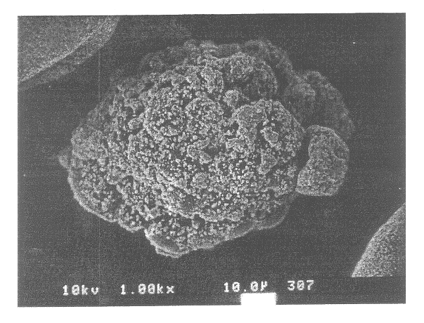
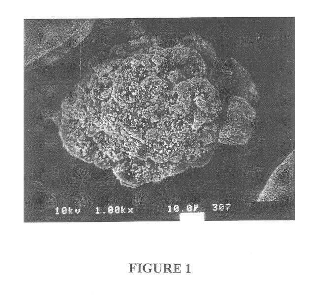
In this Example the basic invention is described as applied to the production of a coating of particles comprising polyester particles coated with stabilized zirconia ceramic layer.

Preparation of the Coated Particles

A 60% solids aqueous dispersion comprising 5.8 wt %, (20 vol %), of a polyester available from Saint Gobain Performance Plastics under the tradename "Ekonol"; 94.2 wt % of yttria-stabilized zirconia, (8 wt % yttria); 0.25 wt % of a surfactant available from Vanderbilt Co. under the trademark "DARVAN.RTM." 821A; 0.25 wt % of a surfactant available from Atlas Powder under the trademark "BRIJ.RTM." 35; 2 wt % of a polyvinyl alcohol temporary binder; and a drop of an antifoam agent available from Air Products under the trademark "TYGO.RTM.".

The average particle size of the stabilized zirconia particles was about 5 micrometers and the average particle size of the Ekonol polyester particles was about 50 micrometers.

The dispersion was spray dried using a Niro model #SD 6.3-R us...


PUM

PropertyMeasurementUnit
particle sizeaaaaaaaaaa

Abstract

Plasma spraying a substrate using particles having a ceramic coating on a combustible core, which may optionally be burned out before spraying, gives a potential for a thicker more conformable protective coat.

Description

The present invention relates to the use of powders in the form of a ceramic shell that may optionally be filled or void in the production of thermally sprayed coatings on substrates.It is well known that placing a temperature-resistant ceramic coating on a substrate can enable the substrate to withstand higher temperatures without deterioration and this has become a common way of protecting substrates as diverse as molds used for casting metals and in the hot zones of turbine engines such as for example on turbine blades for jet engines. The coatings can be applied by a number of techniques but the most frequently used is based on the use of a thermal spray in which the ceramic particles are injected into a plasma jet directed towards the substrate. The heat of the plasma jet melts the ceramic particles and causes them, upon impact with the substrate, to form a ceramic layer with a high degree of uniformity and integrity that is capable of protecting the substrate on which it is co...

Claims


Application Information

Patent Timeline
Patent Type & Authority Patents(United States)
IPC IPC(8): C04B38/00C23C4/04
CPCC04B38/009C23C4/04C04B35/48C04B38/067C04B2111/00482Y02T50/67Y02T50/60
Inventor YU, SUNG H.
Owner SAINT GOBAIN ABRASIVES INC
Learn More