Environmental location system

a technology of environmental location and location system, applied in the direction of navigation instruments, using reradiation, instruments, etc., can solve the problems of increasing the probability of ambiguity, information devices not necessarily each having sufficient information storage (or transmission capacity),

Inactive Publication Date: 2003-08-26
X CYTE
View PDF1 Cites 26 Cited by
  • Summary
  • Abstract
  • Description
  • Claims
  • Application Information

AI Technical Summary

Problems solved by technology

The information devices do not necessarily each have sufficient information storage (or transmission) capacity t...

Method used


Image

  • Environmental location system
  • Environmental location system
  • Environmental location system

Examples


Embodiment Construction

The preferred embodiments of the present invention will now be described with reference the drawings. Identical elements in the various figures are, designated with the same reference numerals.

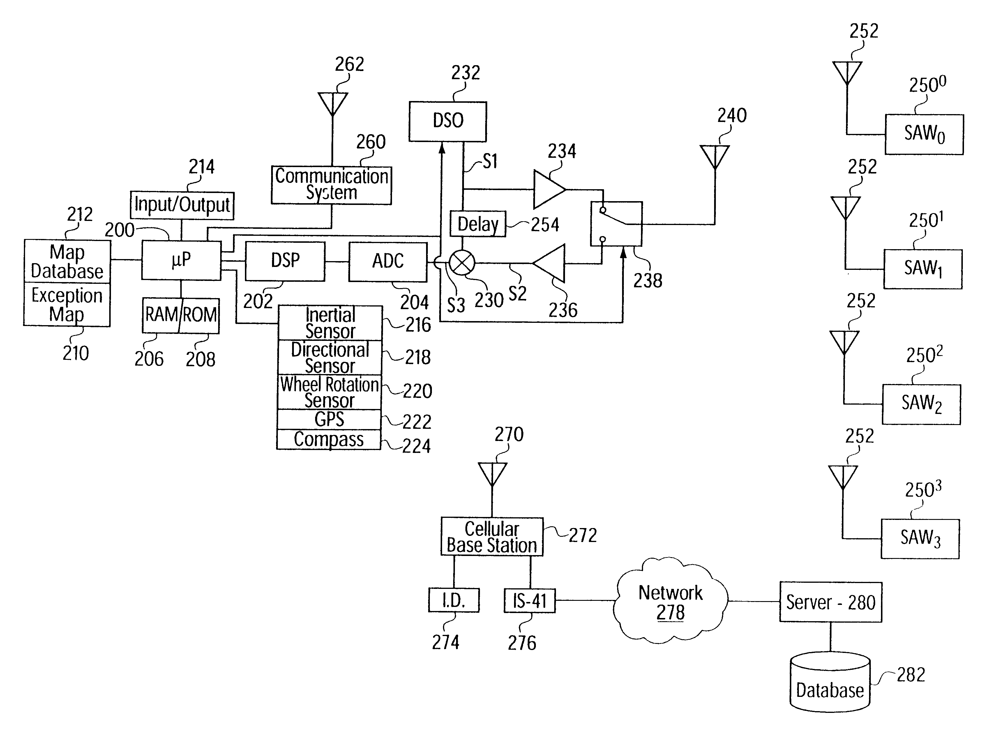
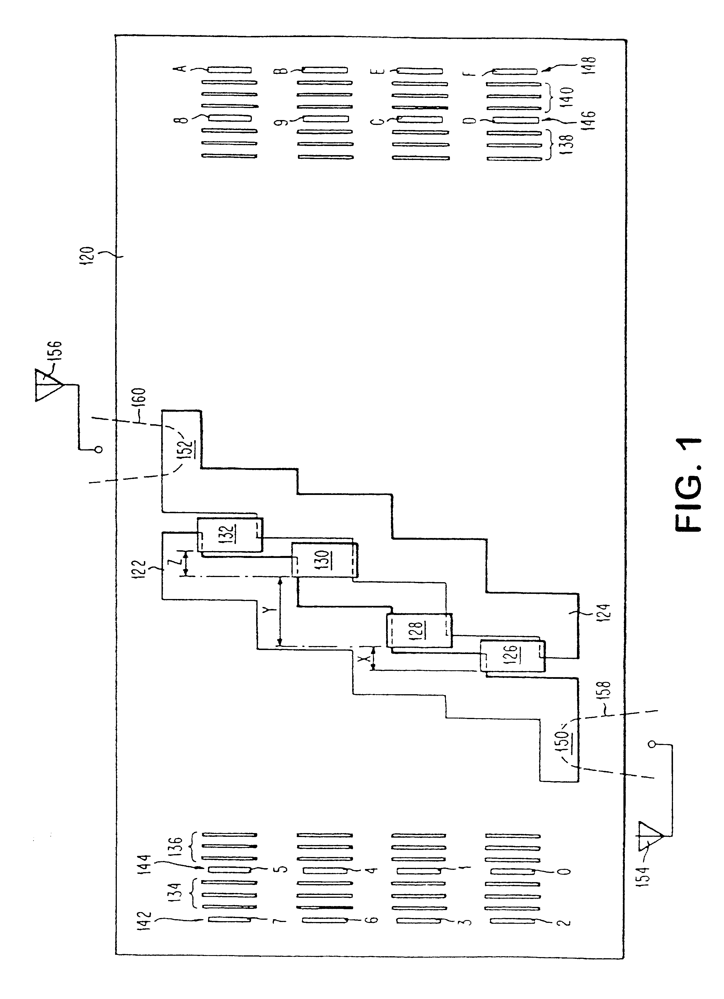
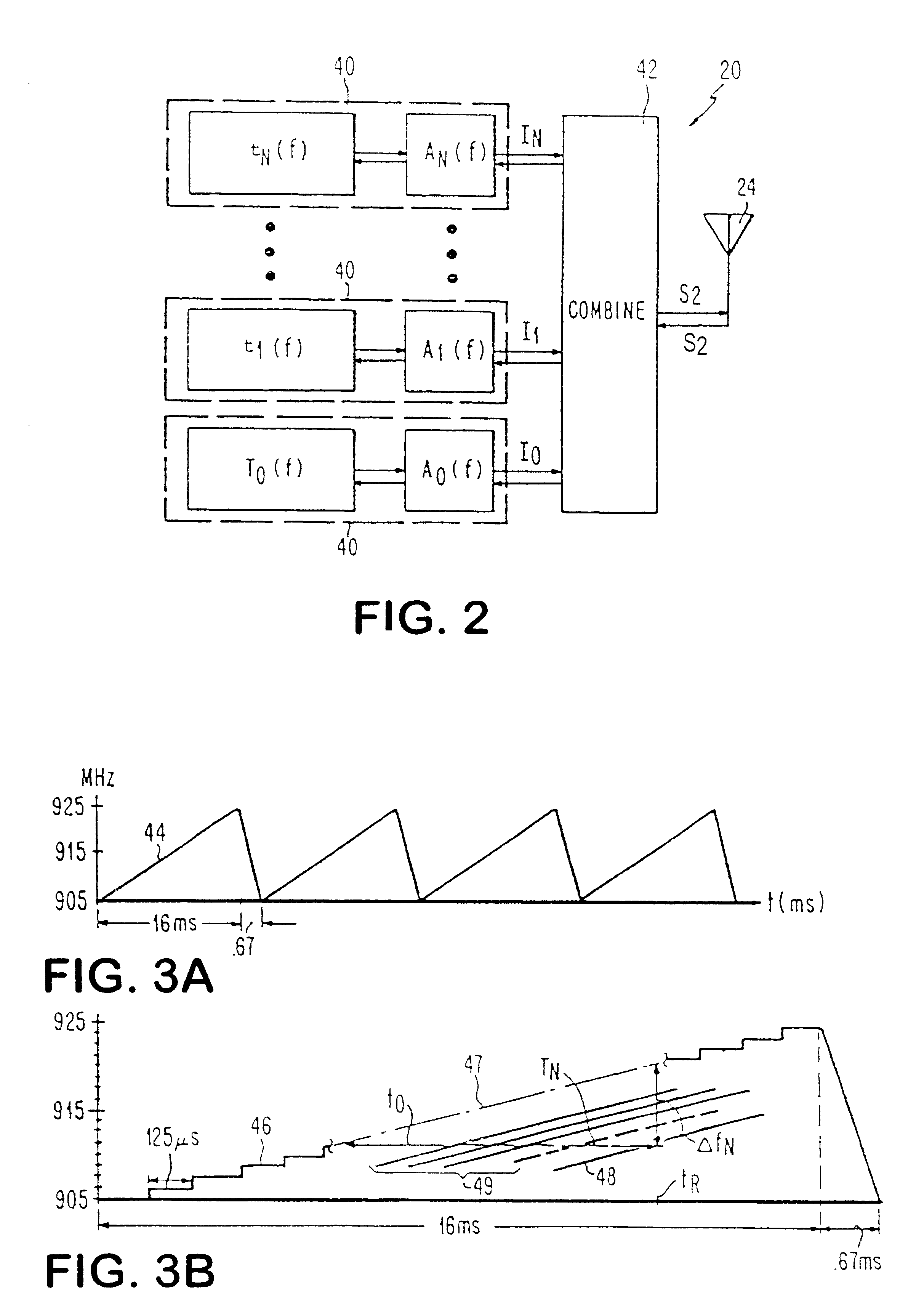
An interrogation system according to the present invention is provided which employs a frequency hopping spread spectrum signal having a pseudorandom sequence which excites each of a set of approximately evenly spaced frequencies once during each repetition. The interrogation signal occupies a band of approximately 20 MHz centered at 915 MHz. The band is divided into 128 discrete frequencies, each of which is maintained for about 125 .mu.S before hopping to a different frequency, which is preferably not an adjacent frequency. The interrogation signal is generated by a digitally controlled oscillator, including a phase locked loop with voltage controlled amplifier. The sequence is selected to evenly spread energy through the band, without concentrating the wave energy in a narrow range for an e...


PUM


Abstract

A system and method for determining a location. The system employs encoded information devices dispersed through the environment, each having, a non-unique code associated therewith. The codes from the encoded information devices are acquired as a reading device passes nearby, and stored. The codes from a proximate set of information devices are correlated with a map or mapping relation to determine one or more consistent positions within the environment. The information devices are preferably passive acoustic wave transponders and the mapping relation may be a pseudorandom sequence or a defined map.

Description

FIELD OF THE INVENTIONA The present invention relates to method and apparatus for determining a location within an environment, and more particularly to a system which derives information from a plurality of passive devices, each having a predetermined location and communicating insufficient information to define the predetermined location.BACKGROUND OF THE INVENTIONA known radio frequency passive acoustic transponder system provides a radio-frequency surface acoustic wave on a piezoelectric substrate which interacts with elements on the substrate to produce an individualized complex waveform response to an interrogation signal. The code space for these devices may be, for example, 2.sup.16 codes, or more, allowing a large number of transponders to be produced without code reuse. These devices consist of a piezoelectric substrate on which a metallized conductor pattern is formed, for example by a typical microphotolithography process, with a minimum feature size of, for example, one...

Claims


Application Information

Patent Timeline
IPC IPC(8): G01S15/00G01S13/87G01S13/00G01S13/75G01S15/87G01S7/40H04Q7/38G01S19/48H04W64/00
CPCG01S7/40G01S13/751G01S13/876G01S15/874H04W64/00G01S2007/4091G01S7/52006G01S7/4091
Inventor NYSEN, PAUL A.
Owner X CYTE
Why Eureka
Try Eureka