Steam generation apparatus and methods

a technology of steam generation apparatus and steam, which is applied in the direction of mechanical equipment, machines/engines, lighting and heating equipment, etc., can solve the problems of not teaching how to calculate heat transfer areas, unable to recognize the possibility of reducing heat transfer surface areas, and unable to introduce operational changes relatively easily to implemen

Inactive Publication Date: 2003-09-16
AIR LIQUIDE AMERICA INC +1
View PDF41 Cites 47 Cited by
  • Summary
  • Abstract
  • Description
  • Claims
  • Application Information

AI Technical Summary

Problems solved by technology

The steam generation research and development community faces an important challenge in the years to come: to produce increased amounts of energy under the more and more stringent constraints of increased efficiency and reduced pollution.
However, the patent fails to teach how to calculate heat transfer areas for the various heat transfer surfaces, and thus does not even mention or recognize the reduction in heat transfer surface areas possible using oxygen-enriched air, or industrially pure oxygen.
However, the very large investment required for a new boiler, together with the already high thermodynamic efficiency of existing boilers make the introduction of operational changes relatively difficult to implement.
The boiler operators are reluctant to introduce modifications in the boiler characteristics, due to possible changes in water vapor properties (temperature, humidity, and the like).
Local vapor superheating may lead to lower heat transfer coefficients, therefore to local boiler tube overheating, eventually causing cracks in boiler tubes.
While the increased flame temperature has a beneficial role on the radiative heat transfer, the diminished flow rates and temperature levels in the convective part of the installation may lead to lower heat transfer rates in this region.
None of these solutions have been readily accepted in the art, for one or more reasons.

Method used


Image

  • Steam generation apparatus and methods
  • Steam generation apparatus and methods
  • Steam generation apparatus and methods

Examples


embodiment 300

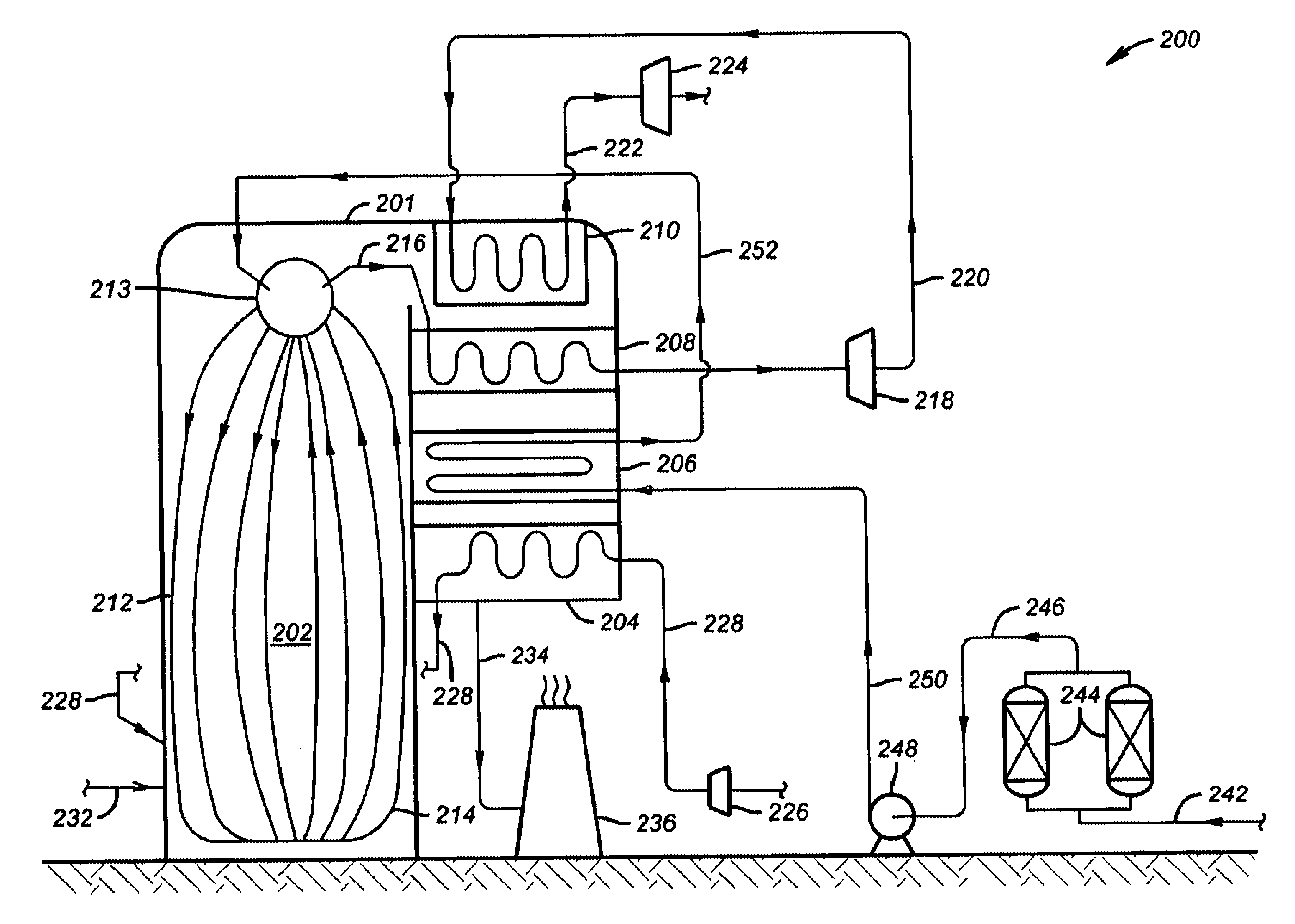
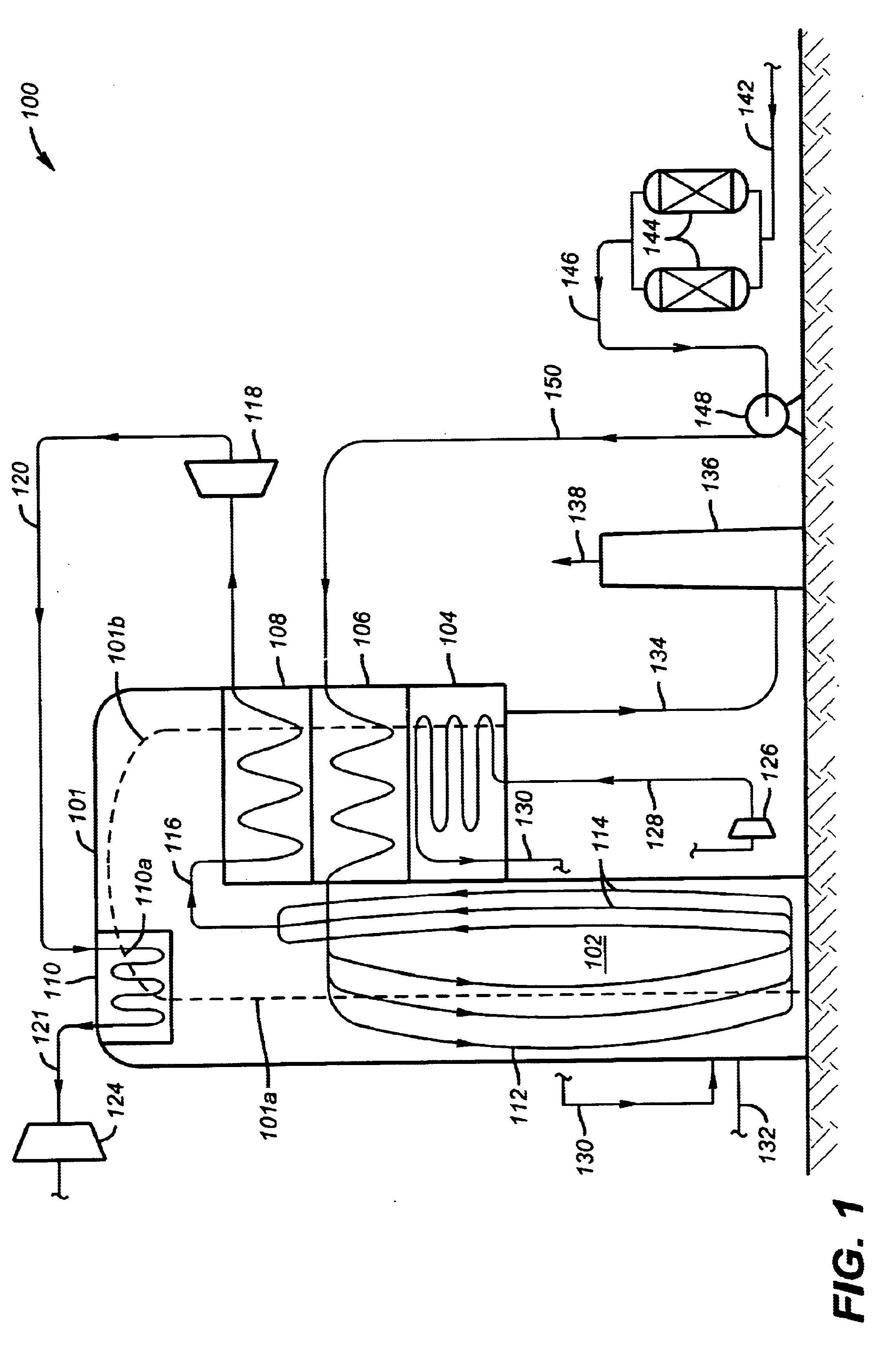
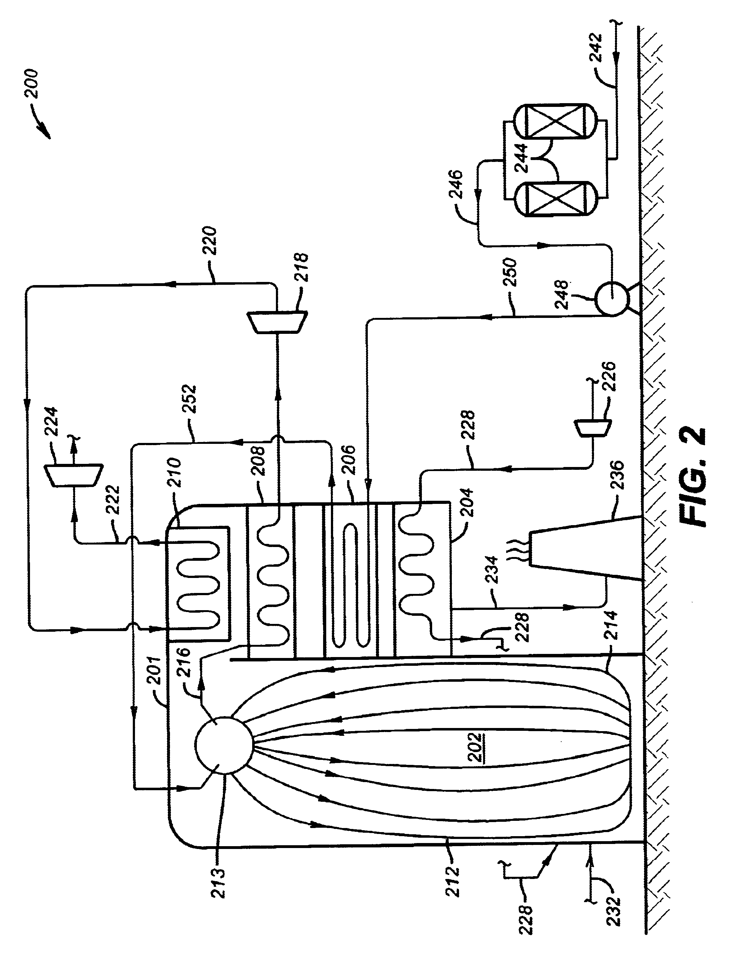
of FIG. 3 also includes an air separation unit at 360, preferably a cryogenic air separation unit or "ASU", comprising a column 371 and a cold box 370. Column 371 is fed compressed, preferably dehumidified air by an air compressor 372 and conduit 374, thus producing a nitrogen-enriched stream 376 and an oxygen-enriched stream 378. Cryogenic air separation is well known in the art and needs no further explanation herein. Other means for separating air may be employed, such as adsorption and membrane units. If a cryogenic ASU is employed, oxygen stream 378 will typically and preferably be liquid, which is then vaporized in a vaporizer 380. Oxygen vapor passes through a conduit 382 and preheater 304 where the oxygen accepts heat from flue gas 334. Fuel enters furnace 302, preferably at multiple locations for multiple burners 341 through conduits 332a and 332b, along with oxidant in conduit 329. For supplying primary oxidant, a portion of non-preheated oxygen is routed through a conduit...

embodiment 400

of FIG. 4 preferably includes the use of both oxygen-enriched air and oxygen as combustion oxidants. An oxygen-enriched air blower or compressor 426 feeds an oxygen-enriched air preheater 404 and oxygen-enriched air is used as the primary oxidant. Oxygen-enriched air is reheated by flue gases 434. Oxygen is compressed or blown via a compressor or blower 425 through conduit 427 and through oxygen preheater 429. Oxygen is then routed to furnace 402 as illustrated in FIG. 4. Fuel enters at 432 to one or more fuel burners 403. Preheated oxygen-enriched air and preheated oxygen are routed to burners 403 as well, promoting efficient burning of fuel in furnace 402. Oxygen may be "lanced" into specific areas of the furnace as well. It will be understood by those having ordinary skill in the boiler art that burner and lance location and positioning are critical to avoid overheating of boiler tubes, membrane walls, furnace walls and roof, to avoid premature corrosion of refractory, and to red...

example

The following example illustrates one preferred method of calculating the heat transfer surface areas of steam generation apparatus of the invention. This example, however, merely illustrates various principles of the invention and is not to be construed as limiting in any fashion the scope of the appended claims.

Principle of the Analysis

This section provides the combustion calculus for an existing boiler (the base case), the analysis of the impact of oxygen enrichment / full oxygen firing on the flue gas temperatures, and evaluation of the heat transfer surface areas necessary for a boiler of the invention that uses oxygen-enriched combustion.

The existing boiler considered, operating with atmospheric air and representing the Base Case, is a SCRRP (Supercritical, Radiant, Reheat and Pressurized). The data sheet of this boiler is summarized in Table 1. It must be noted that the same analysis can be easily extended to any type of boiler. The circulation scheme of the boiler is presented...


PUM


Abstract

Steam generation apparatus and methods are presented that are dedicated to oxygen-enriched air combustion of a fuel, wherein the oxygen concentration of the oxygen-enriched air may range from just above 21 percent to 100 percent. One apparatus comprises an oxygen-enriched air preheater through which oxygen-enriched air flows and exchanges heat indirectly with flue gas, creating a preheated oxygen-enriched air stream. The apparatus further comprises a boiler having a radiant section and a convection section, and other heat transfer units adapted to handle reduced flue gas flow rate and higher temperature flue gases than comparable air / fuel combustion boilers, thus allowing a smaller heat transfer surface area, a more compact design and a higher efficiency.

Description

1. Field of the InventionThis invention concerns oxygen enriched air / fuel combustion steam generation apparatus and methods, more especially in terms of reduced heat transfer surface areas as the percentage of oxygen in the combustion air is increased to 100 percent. In this way a new design of steam generation apparatus is promoted, characterized both by lower investment costs and operating costs.2. Related ArtThe steam generation research and development community faces an important challenge in the years to come: to produce increased amounts of energy under the more and more stringent constraints of increased efficiency and reduced pollution. In order to fulfil both of these requirements, oxygen-enriched air / fuel combustion appears like an attractive candidate, since it has already proven to lead to significant process improvements in other industrial applications, such as fuel savings, production increase or reduced emissions.U.S. Pat. Nos. 6,282,901 and 6,314,896 disclose metho...

Claims


Application Information

Patent Timeline
Patent Type & Authority Patents(United States)
IPC IPC(8): F22B31/00
CPCF22B31/00Y02E20/14
Inventor MARIN, OVIDIUCHARON, OLIVIERPENFORNIS, ERWIN
Owner AIR LIQUIDE AMERICA INC
Why Eureka
Try Eureka