Lens sheet and method for producing the same

a technology of lens sheet and method, which is applied in the direction of non-linear optics, printing, instruments, etc., can solve the problems of significant large proportion of the total power consumption of liquid crystal display apparatus, and prolonging the operation time duration

Inactive Publication Date: 2003-09-30
MITSUBISHI RAYON CO LTD
View PDF14 Cites 71 Cited by
  • Summary
  • Abstract
  • Description
  • Claims
  • Application Information

AI Technical Summary

Problems solved by technology

Recently, in an article which is driven by battery, such as portable personal computer having color liquid crystal display apparatus, portable liquid crystal display apparatus and video-integrated liquid crystal display television, etc. having color liquid crystal display panel, or the like, it has been an obstacle to the prolongation of operation time duration by a charged battery that the power consumption of the liquid crystal display apparatus is significant.
Especially, a rate of the power consumption of the backlight system used in the liquid crystal displays apparatus to the total power consumption of the liquid crystal display apparatus is great.
However, it is not preferable to lower the luminance of the backlight system by suppressing the power consumption of the backlight system, because it becomes hard to observe the liquid crystal display.
In such a lens sheet having the lens portion which is made of activation energy curing resin, there is the following problem: In case where the lens sheet is used as a component of the backlight system, a spot pattern which is considered to be performed on the basis of the deformation of the lens shape caused by the shrinkage of the activation energy curing resin in polymerization when the activation energy curing resin is cured and molded.
The spot pattern becomes an optical defect to deteriorate the optical property of the backlight system.
However, in case of the injection molding method, it is difficult to manufacture a lenticular lens sheet of large size, and therefore this method is restricted to obtain the lens sheet of relatively small size.
In case of the press molding method, since a long time is required for heating / cooling cycle of the resin plate and lens forming mold, many lens forming molds are necessary for mass production of the lens sheet, and therefore enormous expense is necessitated for providing the manufacturing apparatuses in manufacturing the lenticular lens sheet of large size.
However, there is a problem in the method that bubbles are involved in the resin when pouring the resin into the lens forming mold.
Therefore, it is insufficient to take the above conventional method for mass production.
The air bubbles formed once is not easily removed and causes a generation of defect of air bubble in the lens.
However, according to such a method, it is difficult to obtain a lens sheet having uniform thickness, and thus the lens sheet tends to have lower uniformity in thickness, resuting in the problem of causing the deterioration of the lens performance such as distortion of the image, etc.
Additionally, in this method, since the shrinkage of the activation energy curing composition in polymerization is considerable when curing, the lens shape is not sufficiently transferred so that the lens sheet obtained is deviated considerably from the shape designed, or the strain remains in the lens sheet.
Therefore, in a screen provided with the double-sided lenticular lens thus obtained, there occurs a glare which is considered to be caused by lower uniformity in direction of the reflected light of the external light.
The glare is one of the optical defects which deteriorate the optical performance of the screen, etc.
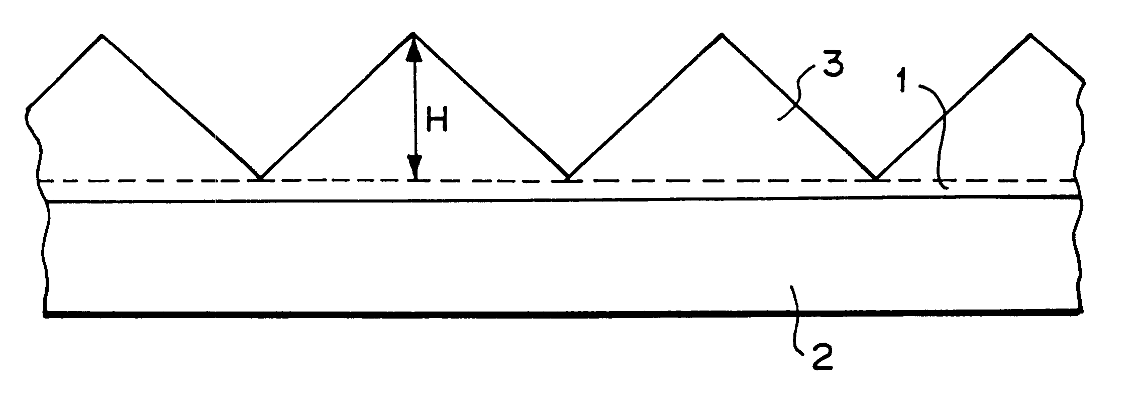
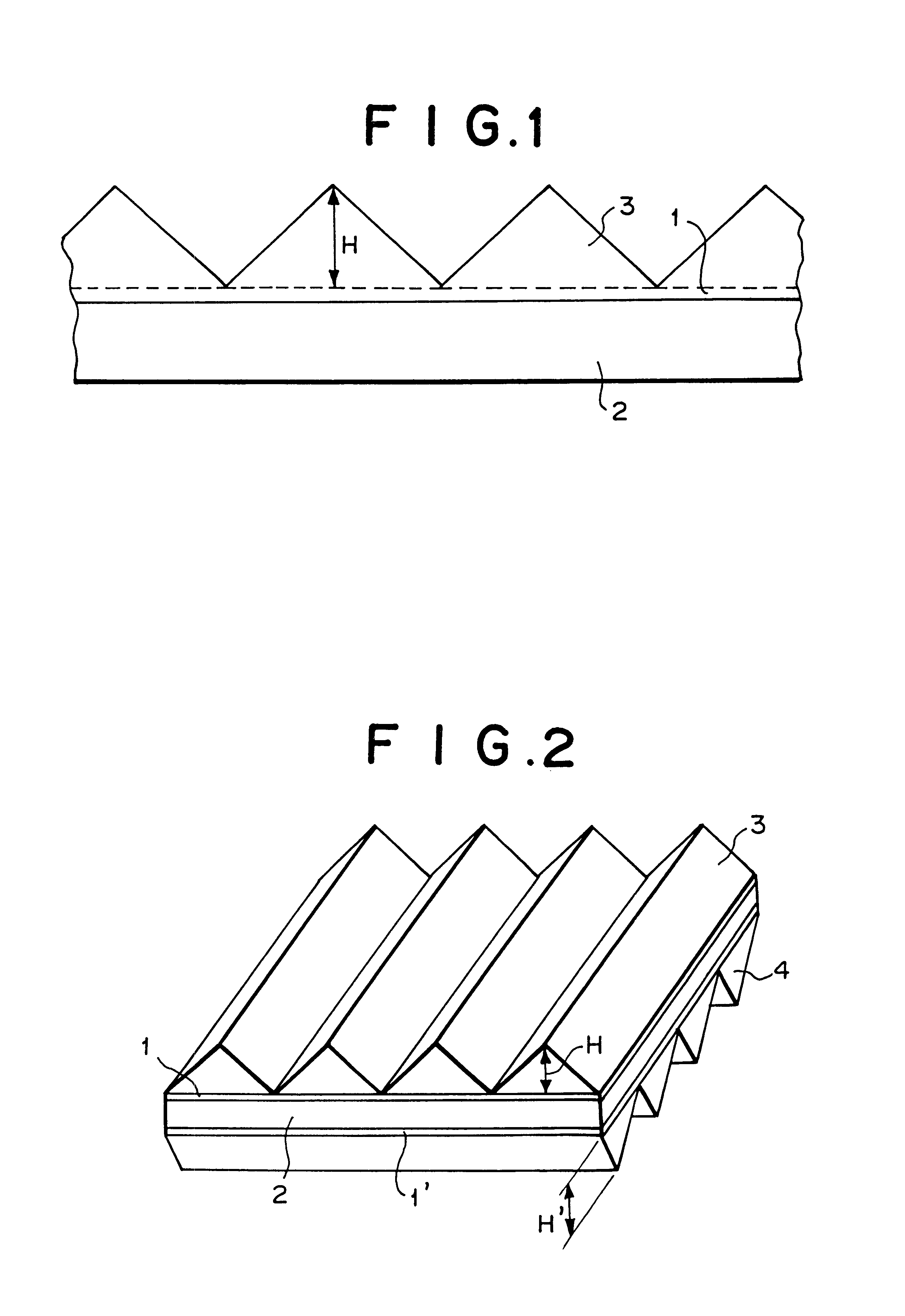
In case of the thickness of the relaxation layers 1, 1' of less than 1% of the height of lens units, the above moderating effect tends to become insufficient.
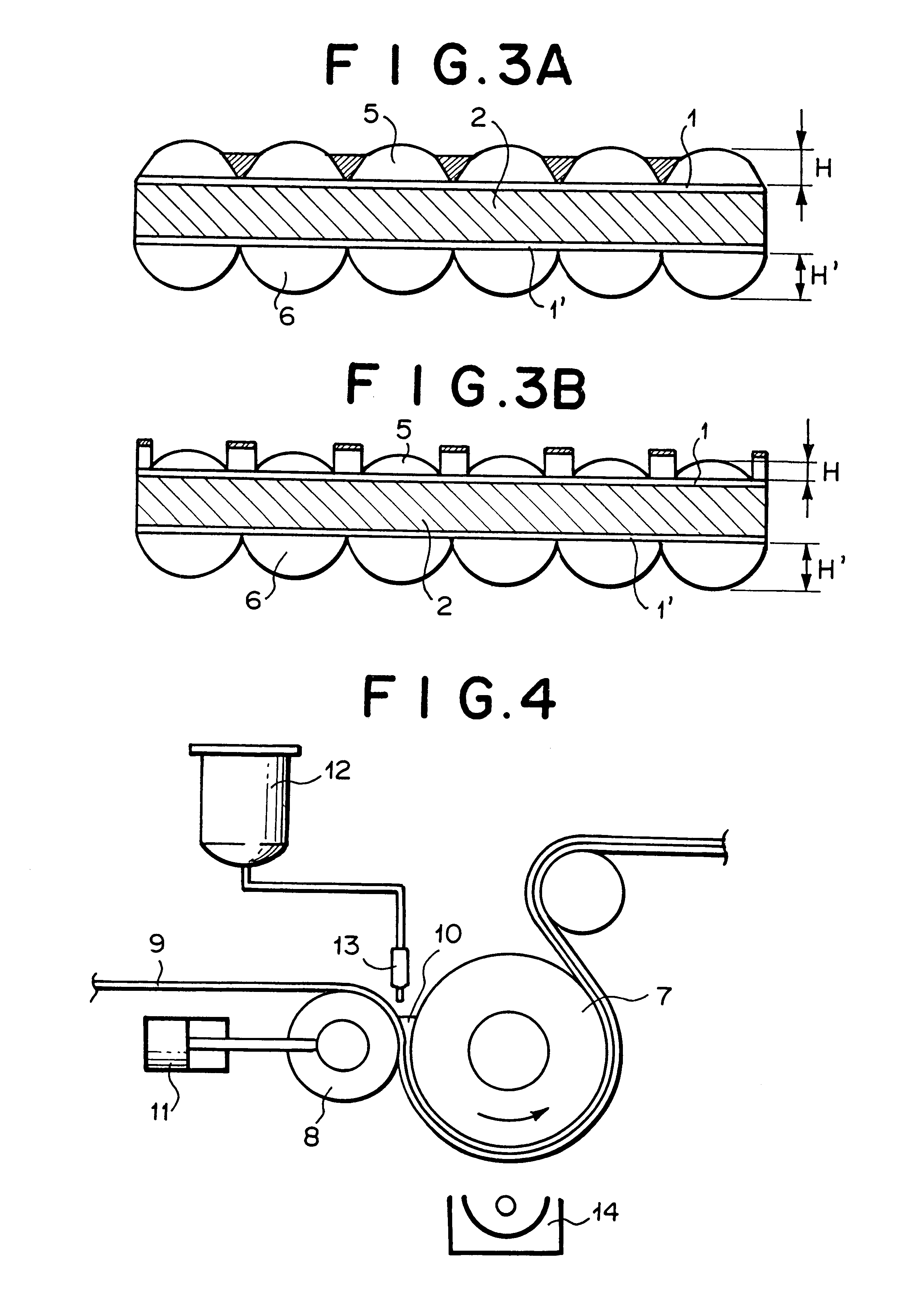
However, when the nip pressure is set to very low, operation of the pressure regulating mechanism 11 tends to become unstable, resulting in ununiformity of the thickness of the relaxation layer 1.
When the forming speed is increased extremely, irradiation amount with the activation energy tends to be reduced, resulting in insufficient curing of the activation energy curing composition 10.
On the other hand, if the viscosity of the activation energy curing composition 10 is greater than 3000 mPa.multidot.S, the activation energy curing composition 10 tends to be fed insufficiently so that the the composition cannot reach the detailed portion of the lens porion transferring pattern of the mold, resulting in the insufficient transferring of the lens shape, occurrence of the defect based on the incorporation of air bubbles into the lens portion, and the lowering of productivity based on the reduction of the forming speed.

Method used


Image

  • Lens sheet and method for producing the same
  • Lens sheet and method for producing the same
  • Lens sheet and method for producing the same

Examples


example 2

A prism sheet (lens sheet) was obtained in the same manner as Example 1 except the following: There was used a cylindrical lens-forming mold which was constituted by a thin-plate lens forming mold with step portion, which had a prism portion transferring pattern and a pair of step portions. The step portions having the width of 10 mm were located at both ends of a thin plate made of brass (JIS Brass Type 3) having a thickness of 1.0 mm and a size of 400 mm.times.690 mm. The prism portion transferring pattern was located at an area between the step portions, where the thickness of the thin plate was reduced by 0.002 mm as compared with the step portions. The prism portion transferring pattern was for use in transfer-forming of a prism portion having a plurality of elongated prisms extending in parallel to each other, the prisms having an isosceles triangular cross section of the vertical angle of 65.degree., the height of 39 .mu.m and the pitch of 50 .mu.m.

The cross section of the pr...

example 3

As shown in FIG. 15, a hard copper plated layer 32 of Vickers hardness of 200 having the thickness of 100 .mu.m was formed on the circumferential outer surface of a core roll 16 made of iron having the diameter of 200 mm and the length of 450 mm. On the copper plated layer 32, there is formed a prism portion transferring pattern for use in transfer-forming of a prism portion having a plurality of elongated prisms extending in parallel to each other, the prisms having an isosceles triangular cross section of the vertical angle of 65.degree., the height of 39 .mu.m and the pitch of 50 .mu.m, to thereby obtain a first cylindrical lens-forming mold. The prism portion transferring pattern had a plurality of elongated prism transferring portions 18 extending in parallel to each other in the circumferential direction of the core roll 16 which is perpendicular to the axial direction of the core roll 16.

On the other hand, as shown in FIG. 16, a thin-plate lens forming mold 15' was provided, ...

example 4

As shown in FIG. 19, a first thin-plate lens forming mold 34 was provided, which has a lenticular lens portion transferring pattern on the surface of a thin plate made of brass (JIS Brass Type 3) having a thickness of 2.0 mm and a size of 1000 mm.times.790 mm. The lenticular lens portion transferring pattern was for use in transfer-forming of a lenticular lens portion for light emitting side having the height of 120 .mu.m and the pitch of 420 .mu.m. The thin-plate lens forming mold 34 was coated with an electroless nickel plated layer in order to prevent various kinds of corrosions. Then, a cylindrical roll 16 made of stainless steel having the diameter of 250 mm and the length of 1000 mm was provided. The thin-plate lens forming mold 34 was wrapped round the roll 16, and fixed on the circumferential outer surface of the cylindrical roll 16 with screws to obtain a first cylindrical lens-forming mold. In the same manner, there was obtained a second cylindrical lens-forming mold which...


PUM

PropertyMeasurementUnit
transparentaaaaaaaaaa
vertical angleaaaaaaaaaa

Abstract

In a lens sheet, a lens portion made if activation energy curing resin such as ultraviolet curing resin has a plurality of lens units, the lens portion is disposed on at least one side of a transparent substrate such as plastic sheet, a relaxation layer is disposed between the transparent substrate and the lens portion, and the thickness of the relaxation layer is within a range of 1% to 30% of the height of the lens units. The relaxation layer is made of activation energy curing resin and formed integrally with the lens portion. The refractive index of the transparent substrate is lower than that of the lens portion. The lens units are elongated prisms each having a substantially triangular cross section.

Description

The present invention relates to a lens sheet such as a prism sheet used for enhancing luminance in normal direction in a back light system, etc. as an illuminating planar light source device of liquid crystal display apparatus, etc., or a double-sided lenticular lens sheet used in a projection screen as a display panel of projection television, microfilm reader, etc., and a method of manufacturing the same, and particularly to a lens sheet having no optical defect such as spot pattern, glare or the like and a method of manufacturing such a lens sheet.DESCRIPTION OF THE RELATED ARTRecently, in an article which is driven by battery, such as portable personal computer having color liquid crystal display apparatus, portable liquid crystal display apparatus and video-integrated liquid crystal display television, etc. having color liquid crystal display panel, or the like, it has been an obstacle to the prolongation of operation time duration by a charged battery that the power consumpti...

Claims


Application Information

Patent Timeline
Patent Type & Authority Patents(United States)
IPC IPC(8): F21V8/00G02B5/04G03B21/62G02F1/13G02F1/1335G02B6/00
CPCG02B5/045G02B6/0053G02B6/0065G03B21/625G02B6/0016G02B6/0038G02F1/133526G02B3/00
Inventor OOKAWA, MAKOTOHAMADA, MASAOMOTONAGA, AKIRAKONAMI, YUKICHIKOGAME, AKIYOSHI
Owner MITSUBISHI RAYON CO LTD
Why Eureka
Try Eureka