Wide or multiple frequency band ultrasound transducer and transducer arrays

a transducer array and ultrasound technology, applied in the direction of transducer types, sound producing devices, diagnostics, etc., can solve the problems of limited energy coupling bandwidth, limited pulse length transmission through the transducer, and traditional ultrasound transducers for medical imaging

Inactive Publication Date: 2003-11-11
ANGELSEN BJORN A J +1
View PDF19 Cites 116 Cited by
  • Summary
  • Abstract
  • Description
  • Claims
  • Application Information

AI Technical Summary

Benefits of technology

The highest sensitivity of the transducer is obtained by minimizing the power transmitted into the backing. This is obtained by either selecting the lowest or highest possible characteristic impedance of the backing material so that the velocity reflection coefficient at the backing interface is close to +1 or -1. Matching layers between the piezoelectric section and backing can be used to reduce the power transmitted into the backing in certain frequency ranges, for example to increase the sensitivity for high frequencies in a band. A problem with such matching is that its resonant nature can reduce the overall operating band of the transducer.
With proper placement of electrodes as discussed under point 2 below, the resonance gives improved phase of the electric impedance of the electric port, hence giving improved sensitivity of the transducer in the resonant bands. According to the invention, thickness resonances in the high impedance section is used to boost the transduction efficiency at the lower and upper frequencies where the load matching section starts to become inefficient, hence increasing the active transduction band of the transducer. To achieve this effect, the thickness of the high impedance section is increased by added elastic layers, introducing resonances of this section on the low and high side of the efficient band of the load matching.

Problems solved by technology

Traditional ultrasound transducers for medical imaging have limitations for such applications in that they are efficient over a limited band of frequencies.
The resonance, however, gives a limited bandwidth of the energy coupling, limiting the minimal pulse length transmitted through the transducer.
Even with these techniques, it is difficult to produce efficient energy coupling bandwidths larger than .about.80% of the center resonance frequency, limiting the bandwidth to .about.35% for 2.sup.nd harmonic imaging, and making it impossible to use higher than the 2.sup.nd harmonic component of the back scattered signal for imaging.
However, the presented patents make less than optimal use of the multilayer design for widest possible bandwidth, and the flexibility for selecting transduction in different frequency bands is limited.
A problem with such matching is that its resonant nature can reduce the overall operating band of the transducer.
Excitation of transversal modes and shear waves in the elastic layers can introduce problems, depending on the dimensions.
Mixtures of polymer with tungsten or other heavy powders can also be used for elastic layers in the high impedance section, albeit they have larger power absorption and hence reduces sensitivity compared to the other solutions.

Method used


Image

  • Wide or multiple frequency band ultrasound transducer and transducer arrays
  • Wide or multiple frequency band ultrasound transducer and transducer arrays
  • Wide or multiple frequency band ultrasound transducer and transducer arrays

Examples


Embodiment Construction

Background Theory

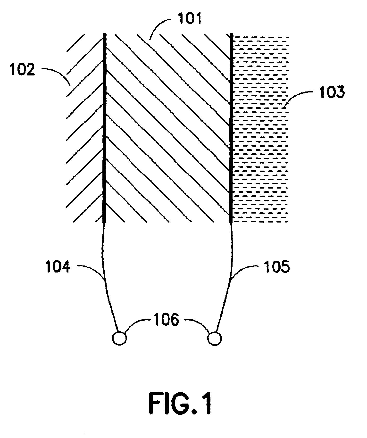
The simplest form of a piezoelectric ultrasound transducer is a piezoelectric plate, illustrated as 101 in FIG. 1, and connects directly to a tissue load material 102. For mechanical support, and also in some cases for acoustic purposes, the transducer is mounted on a backing material 103. For electromechanical coupling, both faces of the plate are coated with electrodes 104 and 105 that forms an electric port 106. The transducer is hence a two-port where the front face constitutes the first, acoustic port, and the electrodes forms the second, electric port.

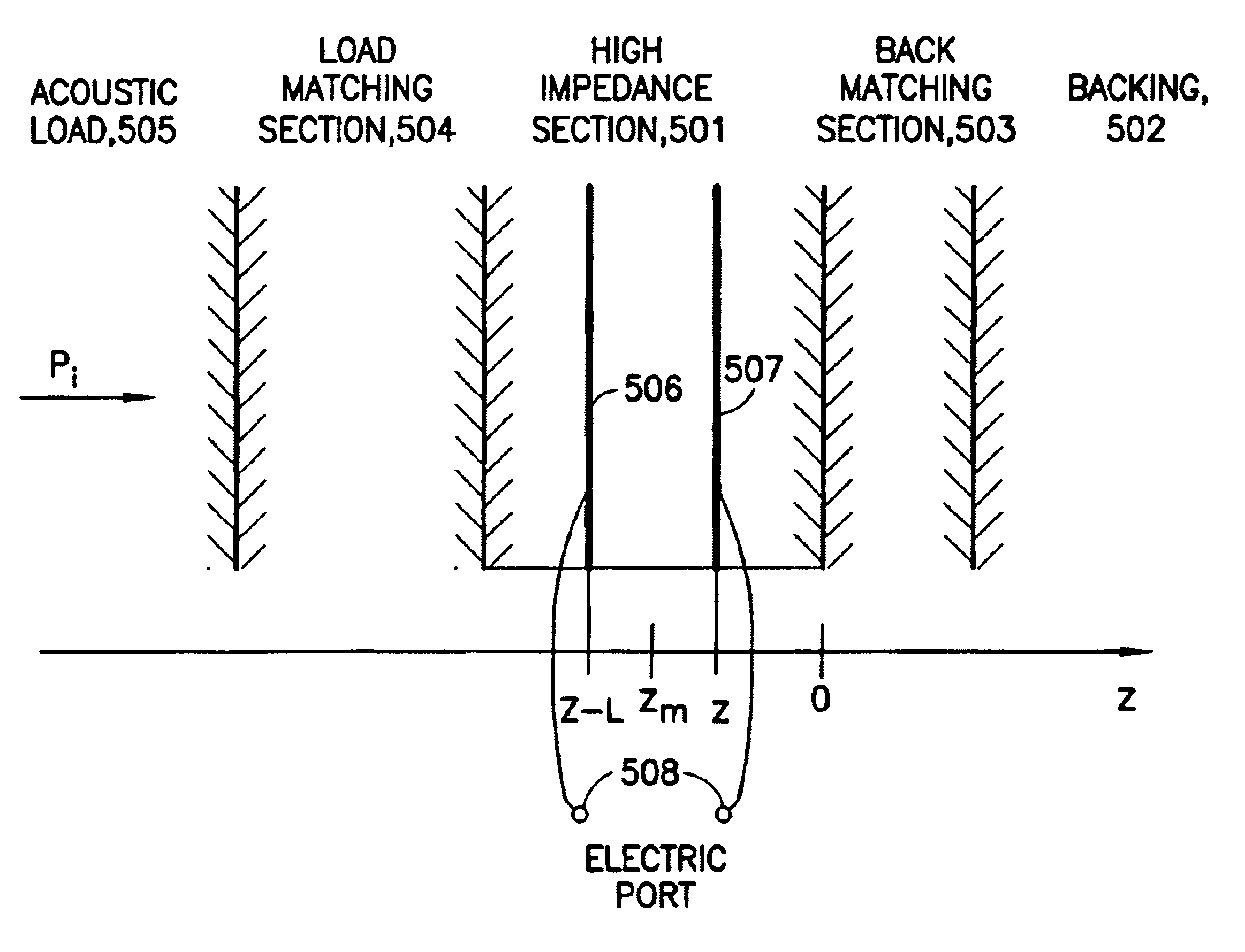
In the following we shall carry through the analysis with continuous, time harmonic signals with angular frequency .omega.. We calculate the values for a transducer with unit area, i.e. the currents, charges and admittances (i.e. the inverse of impedances) are given per unit area. An incident pressure wave in the tissue with amplitude P.sub.i and phase fronts co-planar with the transducer surface, can be represen...


PUM

PropertyMeasurementUnit
frequenciesaaaaaaaaaa
velocity reflection coefficientaaaaaaaaaa
resonance frequencyaaaaaaaaaa

Abstract

Ultrasound bulk wave transducers and bulk wave transducer arrays for wide band or multi frequency band operation, in which the bulk wave is radiated from a front surface and the transducer is mounted on a backing material with sufficiently high absorption that reflected waves in the backing material can be neglected. The transducer is formed of layers that include a high impedance section comprised of at least one piezoelectric layer covered with electrodes to form an electric port, and at least one additional elastic layer, with all of the layers of the high impedance section having substantially the same characteristic impedance to yield negligible reflection between the layers. The transducer further includes a load matching section comprised of a set of elastic layers for impedance matching between the high impedance section and the load material and, optionally, impedance matching layers between the high impedance section and the backing material for shaping the transducer frequency response. For multiband operation, the high impedance section includes multiple piezoelectric layers covered with electrodes to form multiple electric ports that can further be combined by electric parallel, anti-parallel, serial, or anti-serial galvanic coupling to form electric ports with selected frequency transfer functions. Each electric port may be separately transceiver-connected to obtain parallel, anti-parallel, serial or anti-serial port coupling for multi-band transmission, and extremely wide-band reception.

Description

1. Field of the InventionThe present invention is directed to technology and designs of efficient ultrasound bulk wave transducers for wide frequency band operation, and also transducers with multiple electric ports for efficient operation in multiple frequency bands, for example frequency bands with a harmonic relation, where it is possible to receive the 1.sup.st, and / or 2.sup.nd, and / or 3.sup.rd, and / or 4.sup.th harmonic frequency bands of the transmitted frequency band.2. Description of the Related ArtIn medical ultrasound imaging, one uses a variety of center frequencies of the transmitted pulse to optimize image resolution for required image depth. To image deep organs one can use frequencies down to .about.2 MHz, while for shallow depths one can use frequencies higher than 10 MHz.In many cases one also transmits an ultrasound pulse in one band of frequencies, and receive the back scattered signal in a second band of frequencies. This is for example done in 2.sup.nd harmonic i...

Claims


Application Information

Patent Timeline
Patent Type & Authority Patents(United States)
IPC IPC(8): B06B1/06G10K11/02G10K11/00A61B8/00G01N29/24H04R1/00H04R17/00
CPCB06B1/0614H04R17/00G10K11/02
Inventor ANGELSEN, BJORN A. J.JOHANSEN, TONNI F.
Owner ANGELSEN BJORN A J
Why Eureka
Try Eureka