Photon primed non-radioactive gas plasma receiver protector

a non-radioactive, gas-based technology, applied in the direction of reradiation, particle separator tube details, instruments, etc., can solve the problems of high storage, disposal, repair, and high cost of radioactive sources, and achieve the peak and average power handling capability of 3-5 kilowatts

Inactive Publication Date: 2004-02-03
NORTHROP GRUMMAN SYST CORP
View PDF23 Cites 10 Cited by
  • Summary
  • Abstract
  • Description
  • Claims
  • Application Information

AI Technical Summary

Problems solved by technology

However, radioactive sources provide safety hazards and are expensive to store, dispose of, and repair.
However, the peak and average power handling capabilities of these devices are generally limited to 3-5 kilowatts peak and 100-200 watts average, at X-band, due to the need for fast recovery time and low insertion loss.
However, this has the disadvantage of requiring a relatively high voltage power source on the order of 400 V.sub.DC while having a lifetime of only a few hundred hours.
RF primed gas stages are also known in the art, but have been relatively expensive to fabricate.
Generating priming electrons by field emission using a cathode within an array of fine diamond tips which act as field emitting diodes is also a known concept but has the disadvantage of suffering damage during high power RF transmission through the device, thereby limiting its useful lifetime.
Also, while the concept of generating high energy photons by the use of high energy short duration lasers is generally known, they are generally undesirable for radar receiver protector applications.

Method used


Image

  • Photon primed non-radioactive gas plasma receiver protector
  • Photon primed non-radioactive gas plasma receiver protector
  • Photon primed non-radioactive gas plasma receiver protector

Examples


first embodiment

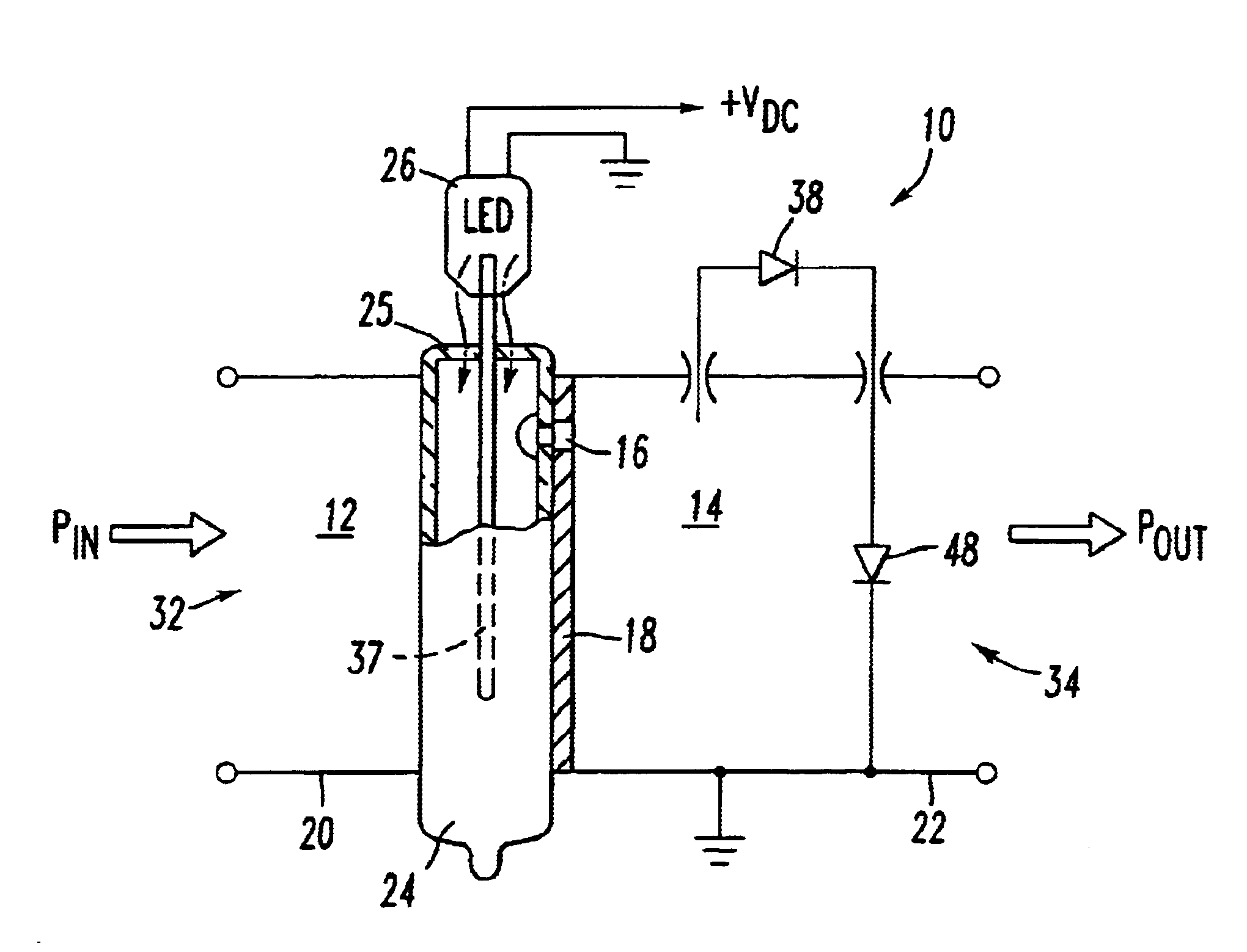
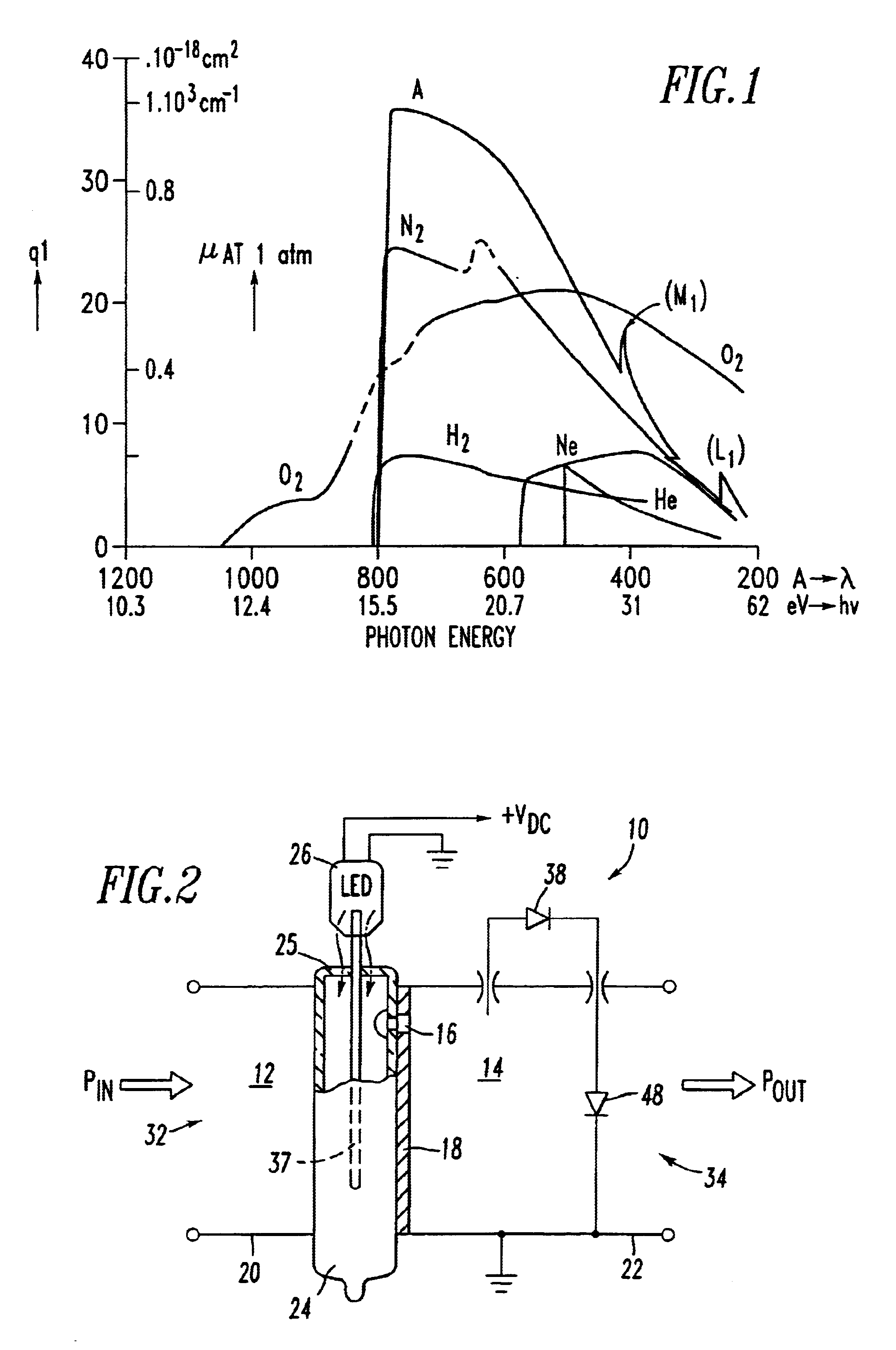
FIG. 2 is an electrical schematic diagram illustrative of a novel photon primed gas plasma stage of a receiver protector in accordance with the subject invention;

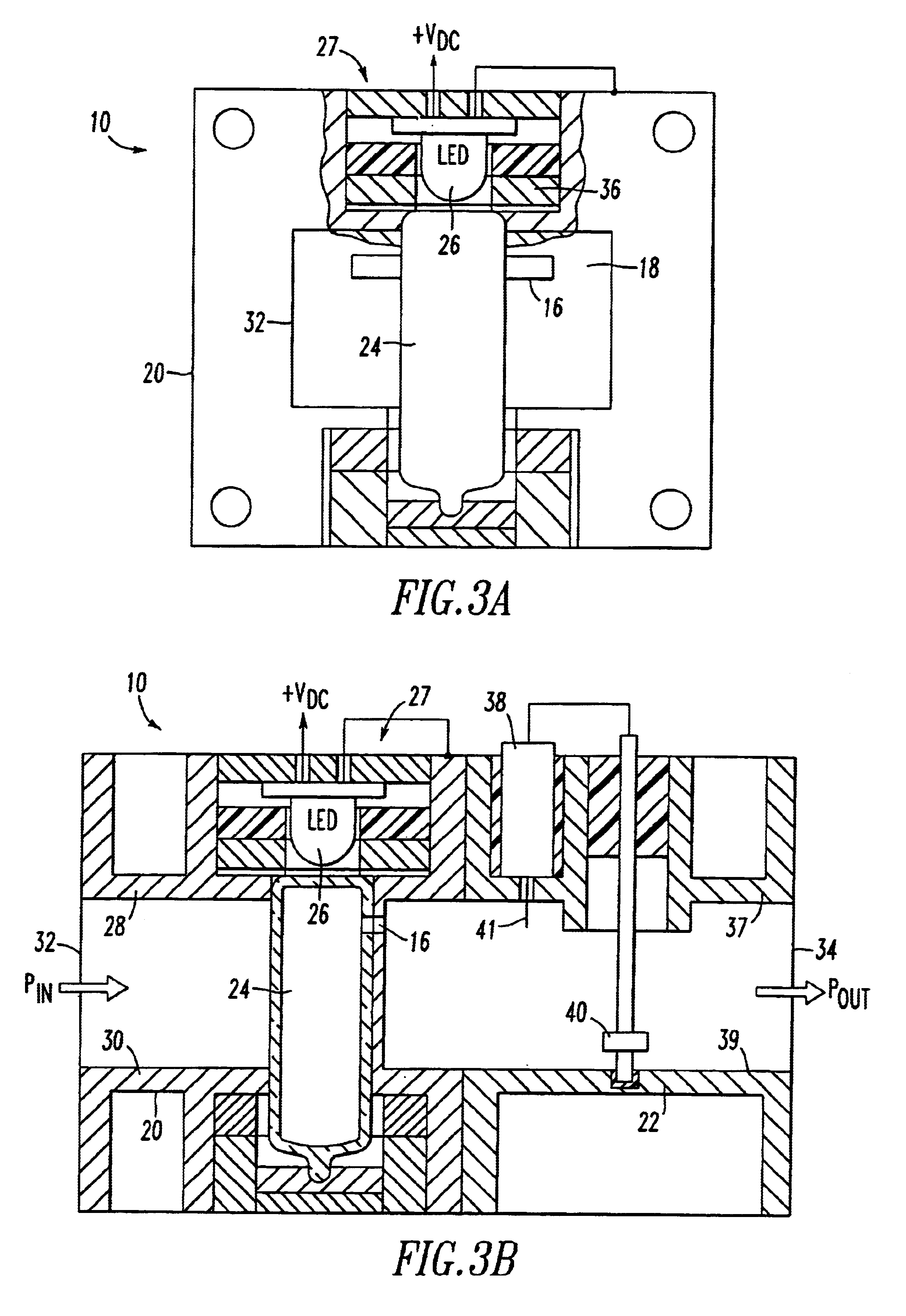
FIGS. 3A and 3B are illustrative of a partial cutaway view and central longitudinal cross sectional view of the first embodiment of the subject invention shown in FIG. 2;

FIGS. 4A and 4B are illustrative of side elevational and central longitudinal cross sectional views of a second embodiment of the subject invention;

third embodiment

FIGS. 5A and 5B are illustrative of a transverse cross sectional view and a sectional view of the subject invention taken along the lines 5--5 of FIG. 5A;

fourth embodiment

FIGS. 6A and 6B are illustrative of top cross sectional and longitudinal cross sectional view of the subject invention;


PUM


Abstract

A gas plasma type receiver protector for a radar system includes a priming device in the form of a miniature high intensity blue light emitting diode (LED) ranging in wavelength from 470 nm to 490 nm, an ultra-violet LED, miniature lamp or laser diode ranging in wavelength from 260 nm to 470 nm.

Description

1. Field of the InventionThe present invention relates to receiver protectors and, more particularly, to receiver protectors for radar systems where high power transmit RF pulses and relatively low power receive RF pulses propagate in a common waveguide type transmission line.2. Description of Related ArtReceiver protectors for present state of the art high power radar systems are generally known and in some systems utilize radioactive tritium or promethium-147 materials to generate seed electrons to initiate gas breakdown. A continuous supply of .beta. emission, i.e. electrons, is provided by such sources and normally have a useful life of more than 30 years, particularly in tritium primed devices. Radioactive sources do not require any external power to generate seeding electrons and, therefore, are useful in passive receiver protectors. However, radioactive sources provide safety hazards and are expensive to store, dispose of, and repair.Solid state receiver protectors using high...

Claims


Application Information

Patent Timeline
Patent Type & Authority Patents(United States)
IPC IPC(8): G01S7/03H01J17/30H01J17/02H01J17/40H01J17/38
CPCG01S7/038H01J17/30H01J17/40G01S7/03
Inventor PATEL, SUMANTRAI D.
Owner NORTHROP GRUMMAN SYST CORP
Why Eureka
Try Eureka