

Process of making a phosphorescent fiber
a technology of phosphorescent fibers and fibers, applied in the field of phosphorescent fibers, can solve the problems of low afterglow brightness level of products, short afterglow extinction time, and strong deprived phosphorescent pigment coating of cloths or textile products prepared in these coating methods
- Summary
- Abstract
- Description
- Claims
- Application Information
AI Technical Summary
Benefits of technology
Problems solved by technology
Method used
Image

Examples
example 2
The phosphorescent particles were encapsulated in the same manner as in Example 1. 20% by weight of the encapsulated phosphorescent particles was mixed with 80% by weight of a PET chip with an intrinsic viscosity of 0.63 and the mixture was pelletized to give master batch. This master batch was compounded with a weight ratio of 40:60 with a mixture of a PET chip with an intrinsic viscosity of 0.63 and a PET chip with an intrinsic viscosity of 0.85 in the weight proportion of 20:80, in combination with 0.5% by weight of a softener (dioctylphthalate) and 0.5% by weight of a dispersing agent (Ca lubricant) based on the weight of the chips used. The mixture composed of master batch, polymer mixture, and additives is then fed into the extruder via a hopper. The mixture was melt-spun at 280.degree. C. to monofilaments with a fineness of 15 deniers. Doubling them gave PET fibers. Also, phosphorescent filaments are cut to produce phosphorescent staple fibers. And then, phosphorescent nonwov...
example 3
The phosphorescent phosphor particles were encapsulated in the same manner as in Example 1. 20% by weight of the encapsulated phosphorescent particles was mixed with 80% by weight of a nylon chip with a relative viscosity of 2.4 and the mixture was pelletized to give master batch. This master batch was compounded with a weight ratio of 40:60 with a mixture of a nylon chip with a relative viscosity of 2.4 and a nylon chip with a relative viscosity of 3.2 in the weight proportion of 20:80, in combination with 0.5% by weight of a softener (dioctylphthalate) and 0.5% by weight of a dispersing agent (Ca lubricant) based on the weight of the chips used. The mixture composed of master batch, polymer mixture, and additives is then fed into the extruder via a hopper. The mixture was melt-spun at 250.degree. C. to monofilaments with a fineness of 15 deniers. Doubling them gave nylon fibers. Also, phosphorescent filaments are cut to produce phosphorescent staple fibers. And then, phosphorescen...
PUM
| Property | Measurement | Unit |
|---|---|---|
| size | aaaaa | aaaaa |
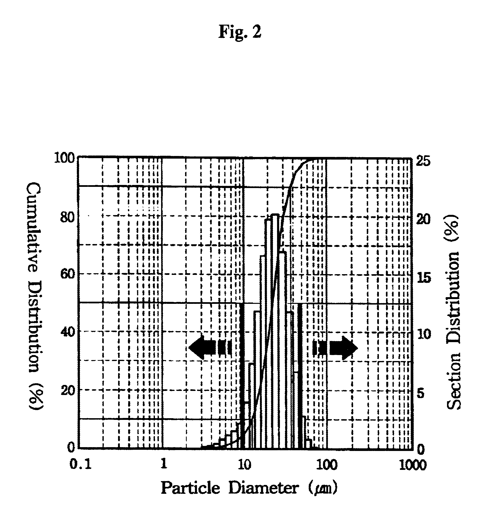
| particle size distribution | aaaaa | aaaaa |
| temperature | aaaaa | aaaaa |
Abstract
Description
Claims
Application Information