Fuel vapor adsorption device of internal combustion engine and method of desorbing fuel vapor from fuel vapor adsorbent

Inactive Publication Date: 2004-03-02
TOYOTA BOSHOKU KK +1
View PDF13 Cites 42 Cited by
  • Summary
  • Abstract
  • Description
  • Claims
  • Application Information

AI Technical Summary

Benefits of technology

In the fourth aspect, because the heating amount is controlled in accordance of the intake air p

Problems solved by technology

As regulations on fuel vapor (hereinafter referred to as "HCs") discharged from a motor vehicle while the vehicle is stopped become more and more stringent, it has become a major issue that HCs diffuse and leak through an inlet port into the atmosphere while the vehicle is stopped.
However, the intake air may not be in uniform cont

Method used


Image

  • Fuel vapor adsorption device of internal combustion engine and method of desorbing fuel vapor from fuel vapor adsorbent
  • Fuel vapor adsorption device of internal combustion engine and method of desorbing fuel vapor from fuel vapor adsorbent
  • Fuel vapor adsorption device of internal combustion engine and method of desorbing fuel vapor from fuel vapor adsorbent

Examples


first embodiment

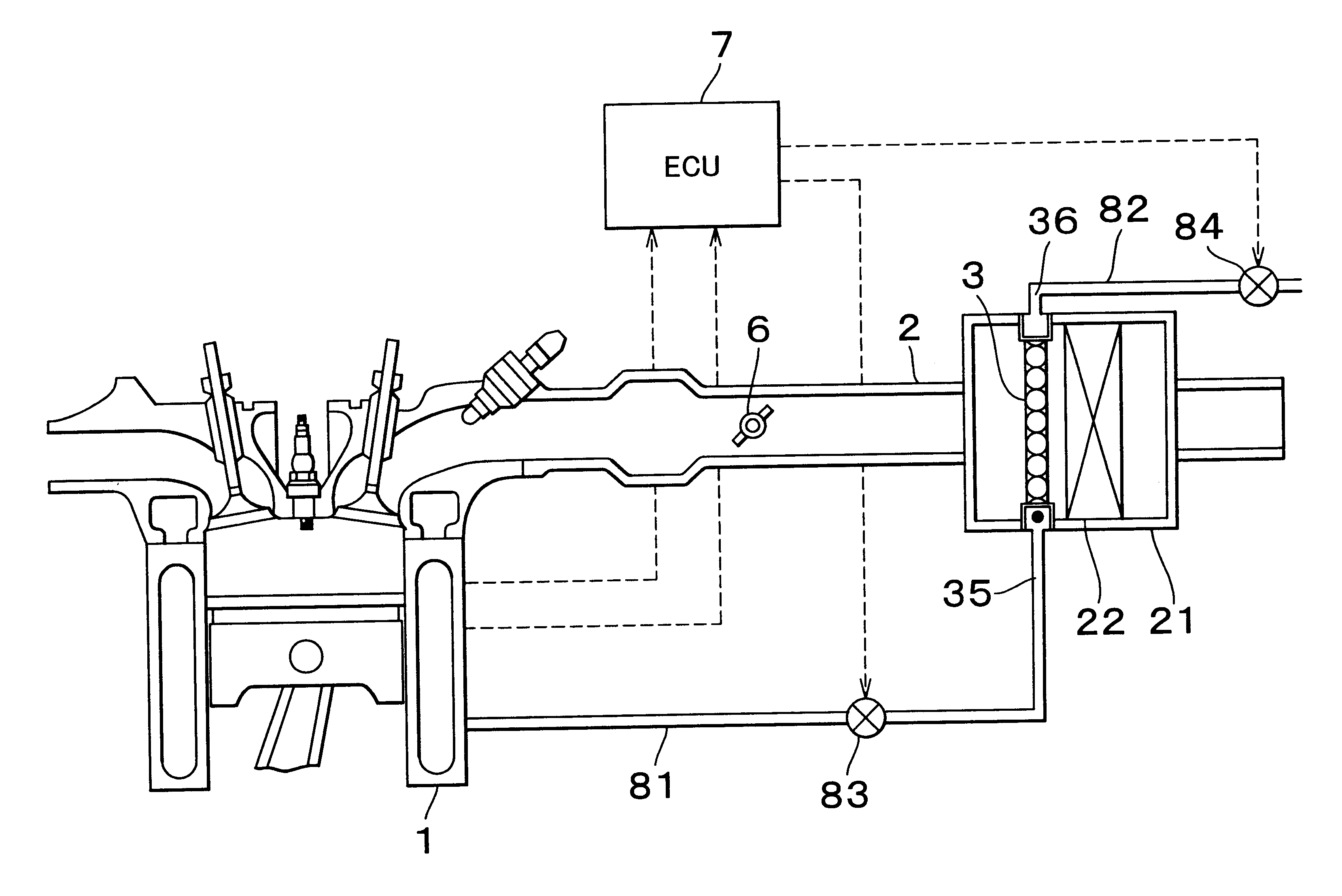
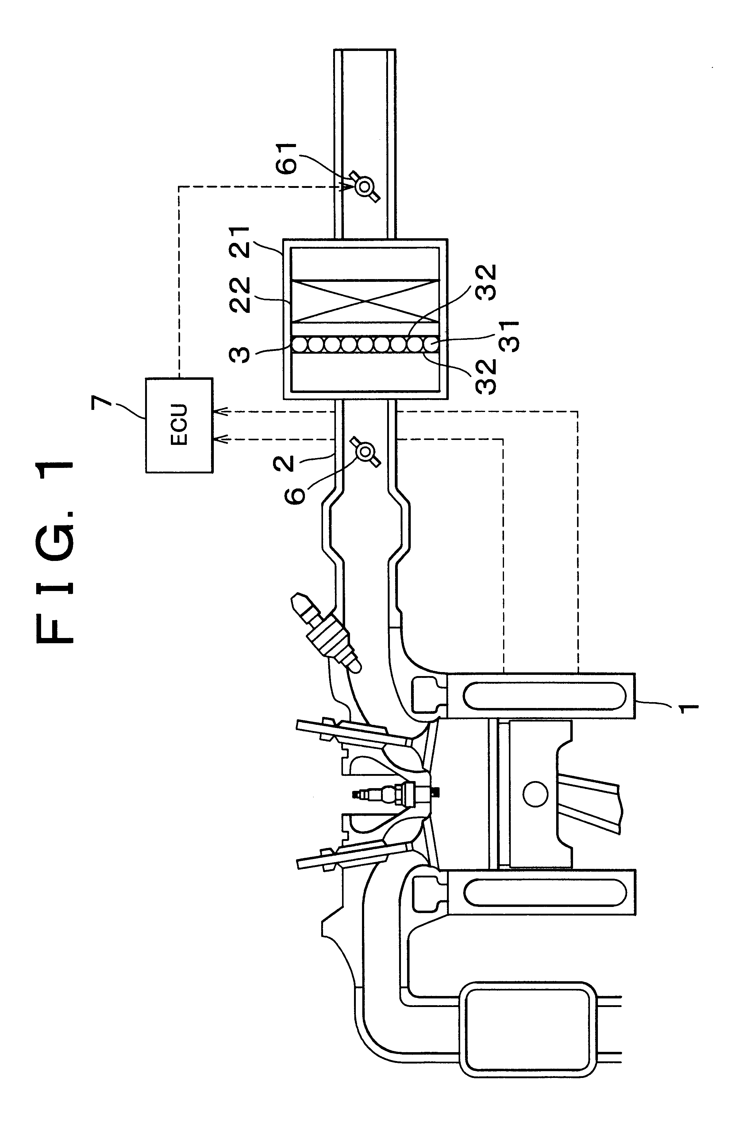
The first embodiment according to the invention will be explained with reference to FIG. 1. An air cleaner 21 is installed in an intake pipe 2 of an internal combustion engine (engine) 1. The air cleaner 21 is provided therein with an air filter 22 having a function of filtering an intake air and an adsorption sheet 3 having a function of adsorbing HCs. The adsorption sheet 3 is disposed on a clean side of the air filter 22 (on a side of a main body of the engine 1) so as to prevent it from being plugged up by dust or other problem. The adsorption sheet 3 has a construction in which an adsorbent (for example, active carbon) 31 is sandwiched between two meshes 32. The mesh size of the mesh is set such that granular powders of the active carbon 31 do not drop through the mesh and the mesh meets an allowable pressure loss value. An intake throttle valve 61 regulates the amount of the intake air upstream of the air cleaner 21. The intake throttle valve 61 is set such at it does not, eve...


PUM


Abstract

An absorbent, such as, for example, an active carbon, is provided in an intake air passage, for example, in an air cleaner, to efficiently adsorb fuel vapor. To ensure that fuel vapor adsorbed into the intake air passage can be efficiently desorbed even when there is only a small amount of the intake air, an intake throttle valve is provided upstream of the adsorbent and an opening of the intake throttle valve is throttled so as to decompress an area near the adsorbent. Desorption of fuel vapor also can be efficiently promoted by using a heater to directly heat the adsorbent in the intake air passage or by heating the intake air to indirectly heat the adsorbent.

Description

INCORPORATION BY REFERENCEThe disclosure of Japanese Patent Application No. 2001-297678 filed on Sep. 27, 2001, including the specification, drawings and abstract is incorporated herein by reference in its entirety.BACKGROUND OF THE INVENTION1. Field of InventionThe invention relates to a fuel vapor adsorption apparatus disposed in an intake air passage of an internal combustion engine in order to adsorb fuel vapor and a method of desorbing fuel vapor from a fuel vapor adsorbent.2. Description of Related ArtAs regulations on fuel vapor (hereinafter referred to as "HCs") discharged from a motor vehicle while the vehicle is stopped become more and more stringent, it has become a major issue that HCs diffuse and leak through an inlet port into the atmosphere while the vehicle is stopped. HCs are generated when residual fuel left in an engine and fuel that leaks from an injector vaporize. There has been devised a device, in which an HC adsorbent in the form of, for example, a filter acc...

Claims


Application Information

Patent Timeline
IPC IPC(8): F02M25/08F02M35/10F02M31/04F02M31/08F02M31/125F02M31/135F02M31/14F02M31/16F02M33/00F02M33/04F02M33/06
CPCF02M25/08F02M35/10019F02M35/10216F02M35/10275
Inventor HONDA, MINORUODA, KOUICHIKATO, NAOYATAKEYAMA, MASAKIINUZUKA, YOSHINORIAMANO, NORIYASUNISHIMOTO, TAKASHI
Owner TOYOTA BOSHOKU KK
Why Eureka
Try Eureka