System and method for determining the location of a catheter during an intra-body medical procedure

a technology which is applied in the field of system and method for determining the location of a catheter during an intra-body medical procedure, can solve the problems of not teaching the co-establishment of the location of the imaging apparatus or the image, visual memorization, and is therefore highly subjective, and is hardly or not at all imageabl

Inactive Publication Date: 2004-03-23
TYCO HEALTHCARE GRP LP
View PDF26 Cites 679 Cited by
  • Summary
  • Abstract
  • Description
  • Claims
  • Application Information

AI Technical Summary

Problems solved by technology

However, the prior art fails to teach the co-establishment of the location of the imaging apparatus or the image coordinates, such that points-of-interest in the body are recordable, displayable and most importantly projectable onto an image of the body of the patient taken from another angle during the same procedure or during another, later procedure.
Cardiac arrhythmia is the result of improper progression of electrical signals for contraction along the heart tissue.
According to the present methodology, knowing the three dimensional location of the steerable catheter tip within the heart cavity depends on a large number of data parameters and visual memorization and is therefore highly subjective.
In addition, the heart tissue itself is transparent to X-rays and it is therefore hardly or not at all imageable.
These difficulties are more critical when it is required to return accurately to a location already mapped for further treatment.
This, in turn, is associated with a major limitation because it is in many cases advantageous to image the patient from different angles, so as to obtain images of different planes thereof.
Yet, any catheter location data (point-of-interest) recorded in context of an image obtained from a certain relative orientation is non-projectable onto images obtained from other orientations, because the location in space of the imaging device is not monitored or established.
The above apparatuses and methods, while teaching the recording of heart functionality for identifying active sites therein, fail to teach the recording of other points-of-interest, such as, but not limited to, points to which ablation has been applied, therefore preventing the accurate relocation of such sites for nearby ablation as required from time to time.
Otherwise, such information is available only under constant use of fluoroscopy, which is undesirable due to the radiation to which both patient and staff are exposed.
Consequently, selecting the location of the ablation catheter's tip as the desired location for treatment, as is normally done, is not necessarily accurate and may by harmful.
Orientation of the catheter to a desired location using this type of imaging is difficult since the soft cardiac tissues are not readily imageable, and as such the physician is provided with minimal information as to the structure of the organ.
Therefore, when the two images, fluoroscopy and ultrasound, are shown without any correction, their integration and assimilation in the physician's mind into valuable data is difficult.
Planning such a path and guiding a tool with which the treatment is performed along that path are difficult, particularly in complex three-dimensional areas of tissue within a dynamically-changing organ such a beating heart.
During the course of such procedures an ablating catheter tip can and often does displace from the desired treatment location, resulting in an inaccurate, ineffective and often damaging ablation.
When movements of a catheter tip are experienced during the application of ablative treatment to the tissue, a complex shape of ablated region results.
However, if insufficient contact between one or more of the electrode contacts and the tissue occurs, a non-uniform ablation pattern results, and as a result the ablation procedure has to be repeated.
In addition, it is sometimes necessary to ablate a linear pattern which is longer than the length generatable by a single application of a multi-electrode catheter.
Such a linear pattern can only be obtained by multiple applications which again requires accurate repositioning of the catheter.

Method used


Image

  • System and method for determining the location of a catheter during an intra-body medical procedure
  • System and method for determining the location of a catheter during an intra-body medical procedure
  • System and method for determining the location of a catheter during an intra-body medical procedure

Examples


Embodiment Construction

Reference is now made to the following example, which together with the above descriptions, illustrate the invention in a non limiting fashion.

This example is directed at measuring parameters required for fluoroscope imaging according to the present invention.

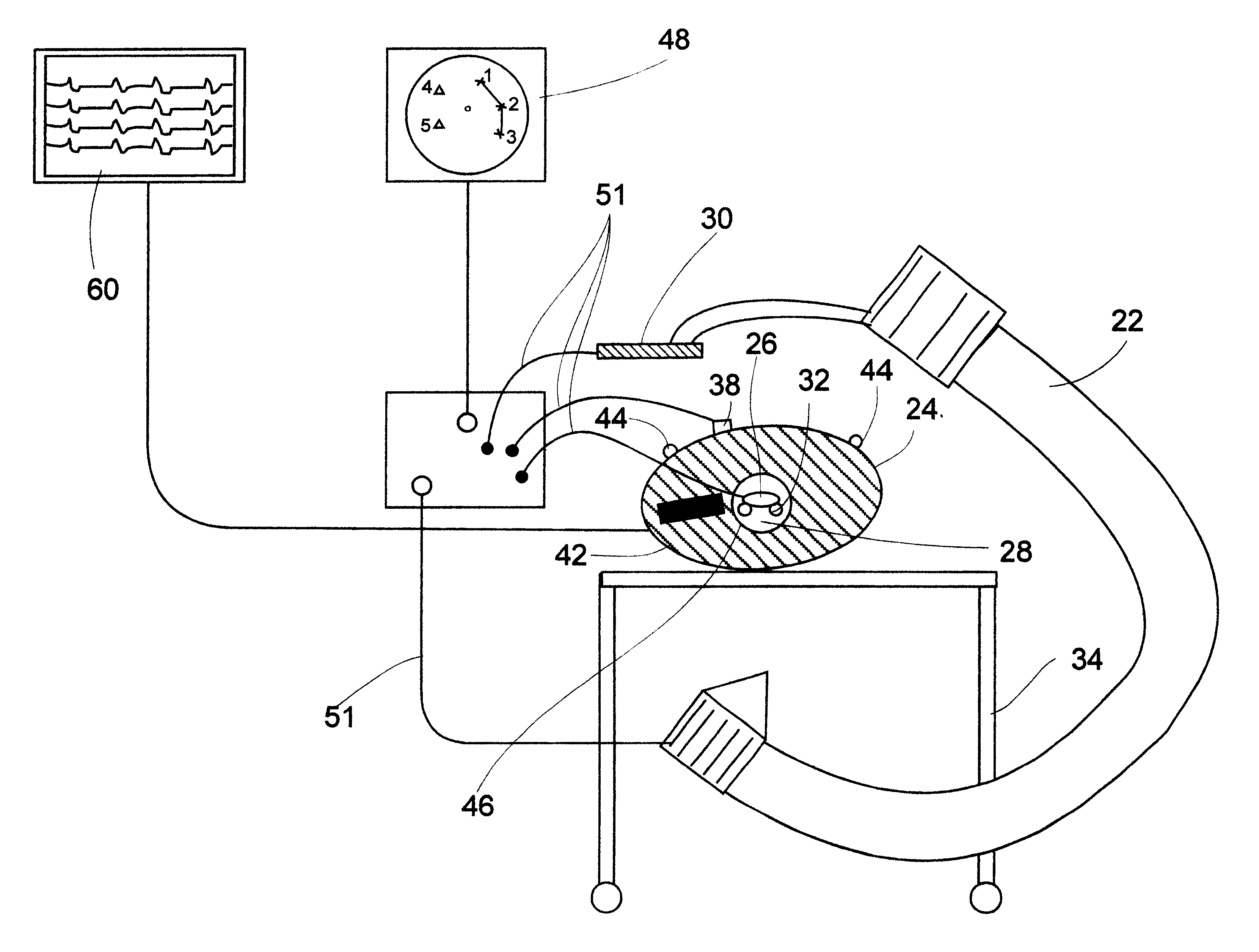
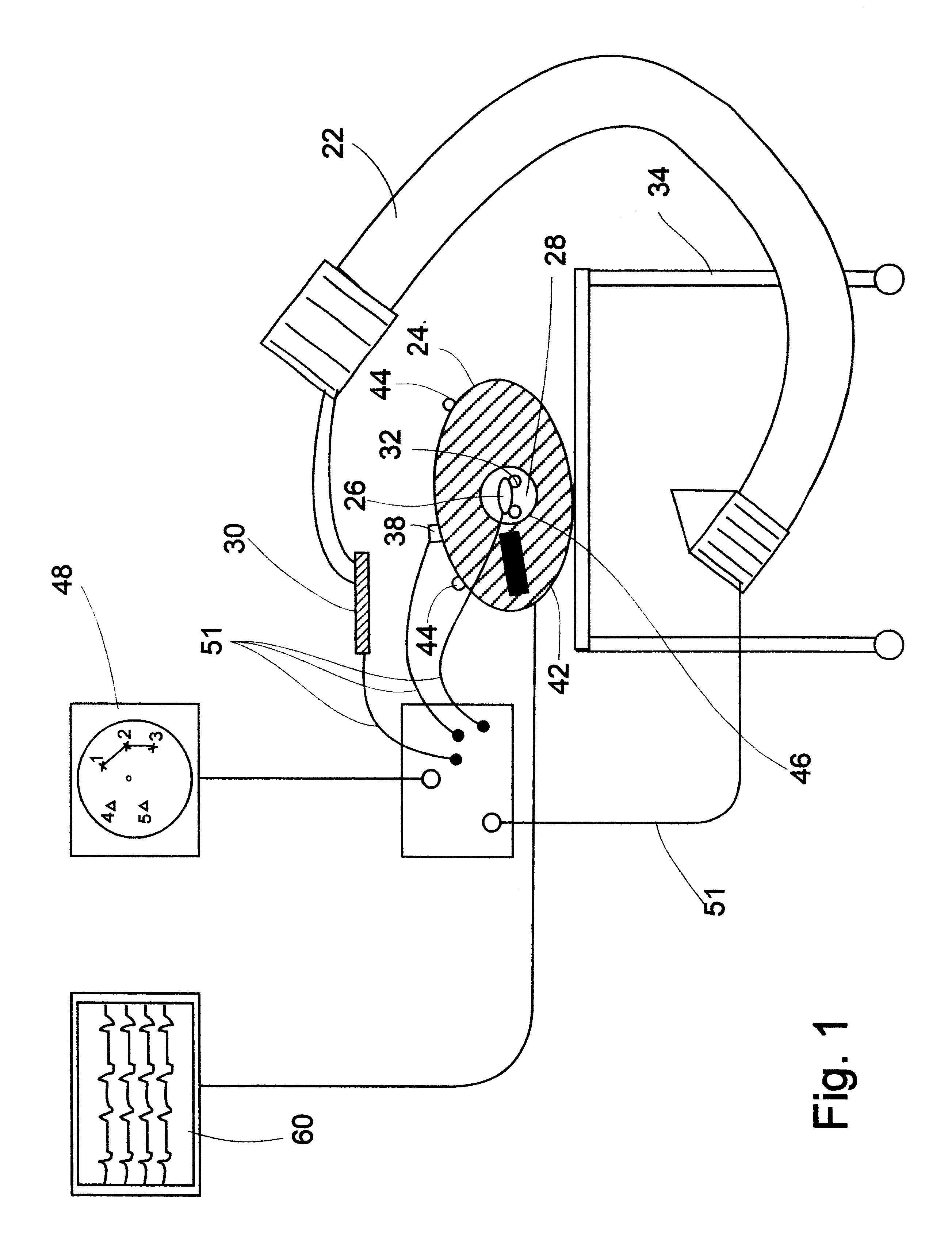
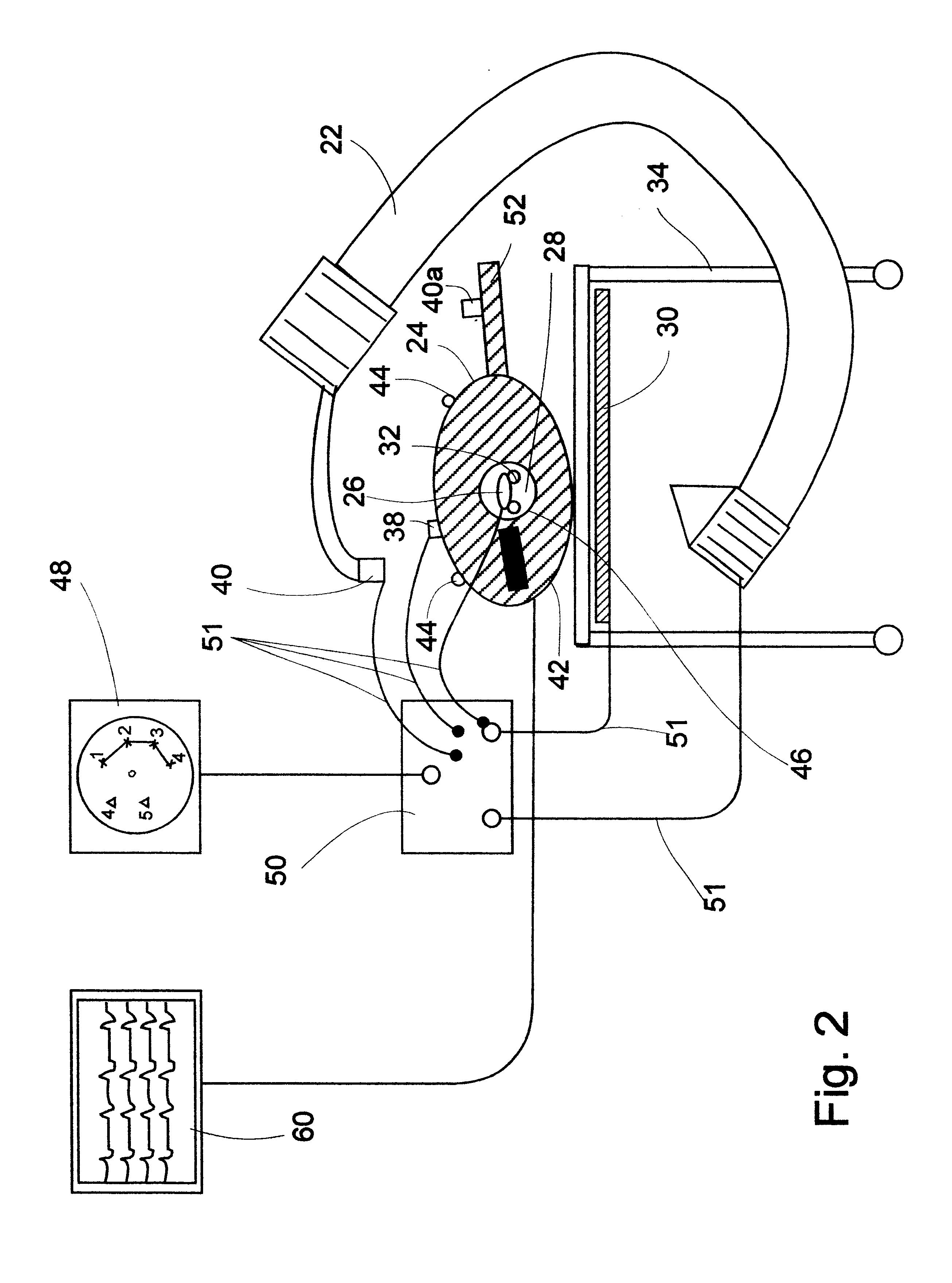
Assume a first system of coordinates {K,L,F} which defines the location of an of an imaging instrument, say a fluoroscope having a source and an imaging plane.

Assume a second system of coordinates {X,Y,Z} which defines the location of a location implement.

Define {k.sub.0,l.sub.O,f.sub.0 } as the origin of the {X,Y,Z} system as reflected on the {K,L,F} system of coordinates.

The {X,Y,Z} system is rotated with respect to the {K,L,F} system.

The rotation operator, T, is a matrix of 3.times.3 terms which satisfies the orthonormality condition.

The location implement implemented in the catheter is at {x,y,z} as measured in the {X,Y,Z} system.

The location implement is imageable and therefore will be reflected on the image plane of the i...


PUM


Abstract

A system and method of displaying at least one point-of-interest of a body during an intra-body medical procedure. The method is effected by (a) establishing a location of the body; (b) establishing a location of an imaging instrument being for imaging at least a portion of the body; (c) defining at least one projection plane being in relation to a projection plane of the imaging instrument; (d) acquiring at least one point-of-interest of the body; and (c) projection said at least one point-of-interest on said at least one projection plane; such that, in course of the procedure, the locations of the body and the imaging instrument are known, thereby the at least one point-of-interest is projectable on the at least one projection plane even in cases whereby a relative location of the body and the imaging instrument are changed.

Description

FIELD AND BACKGROUND OF THE INVENTIONThe present invention relates to a system and method of recording and displaying in context of an image a location of at least one point-of-interest in a body during an intra-body medical procedure, and, more particularly, to a system and method which enable to simultaneously obtain location data of the body, of a catheter inserted into the body and of an imaging instrument used to image the catheter and the body, to thereby record and display in context of the image the location of the at least one point-of-interest in a body even when the relative location between any of the above locatable items is changed.In many cases patients undergo procedures in which a catheter is inserted into their body (e.g., into a body cavity, such as, but not limited to, heart, lung, kidney, liver, bladder and brain cavities). It is in many cases desirable to follow the location of the catheter within the body. This is especially the case when the catheter is a pro...

Claims


Application Information

Patent Timeline
Patent Type & Authority Patents(United States)
IPC IPC(8): A61B5/06A61B19/00A61B5/296A61B6/00A61B6/12A61M25/00A61M25/01G06T1/00G06T7/60
CPCA61B5/06A61B19/52A61B90/36A61B5/062A61B5/064
Inventor GILBOA, PINHASTOLKOWSKY, DAVIDHOLLANDER, DAVID
Owner TYCO HEALTHCARE GRP LP
Why Eureka
Try Eureka