Liquid-solids circulating fluidized bed

Inactive Publication Date: 2004-04-06
UNIVERSITY OF WESTERN ONTARIO
View PDF6 Cites 63 Cited by
  • Summary
  • Abstract
  • Description
  • Claims
  • Application Information

AI Technical Summary

Benefits of technology

The liquid-solids separator 46 in the illustrated arrangement is a hydraulic (but can be any other type of separator) cyclone, which separates the regenerated particles 18 from the extract 28. The extract outlet 48 is located on the separator preferably at the same level as that of the raffinate outlet 44 on the top of the first fluidized bed 10 to maintain the pressure balance between the second fluidized bed 12 and the first fluidized bed 10. To prevent the loss of particles through the extract outlet, a stainless steel mesh (not shown) is preferably used to cover the extract outlet 48.
The top washing section 50 comprises of the funnel bottom of the separator and return pipe 17.

Problems solved by technology

The magnetically stabilized fluidized bed system is considered to be complicated and costly.
This system, although simple and easy to control, has the disadvantage of a stirred tank system--the ion exchange efficiency is low and la

Method used


Image

  • Liquid-solids circulating fluidized bed
  • Liquid-solids circulating fluidized bed

Examples


Embodiment Construction

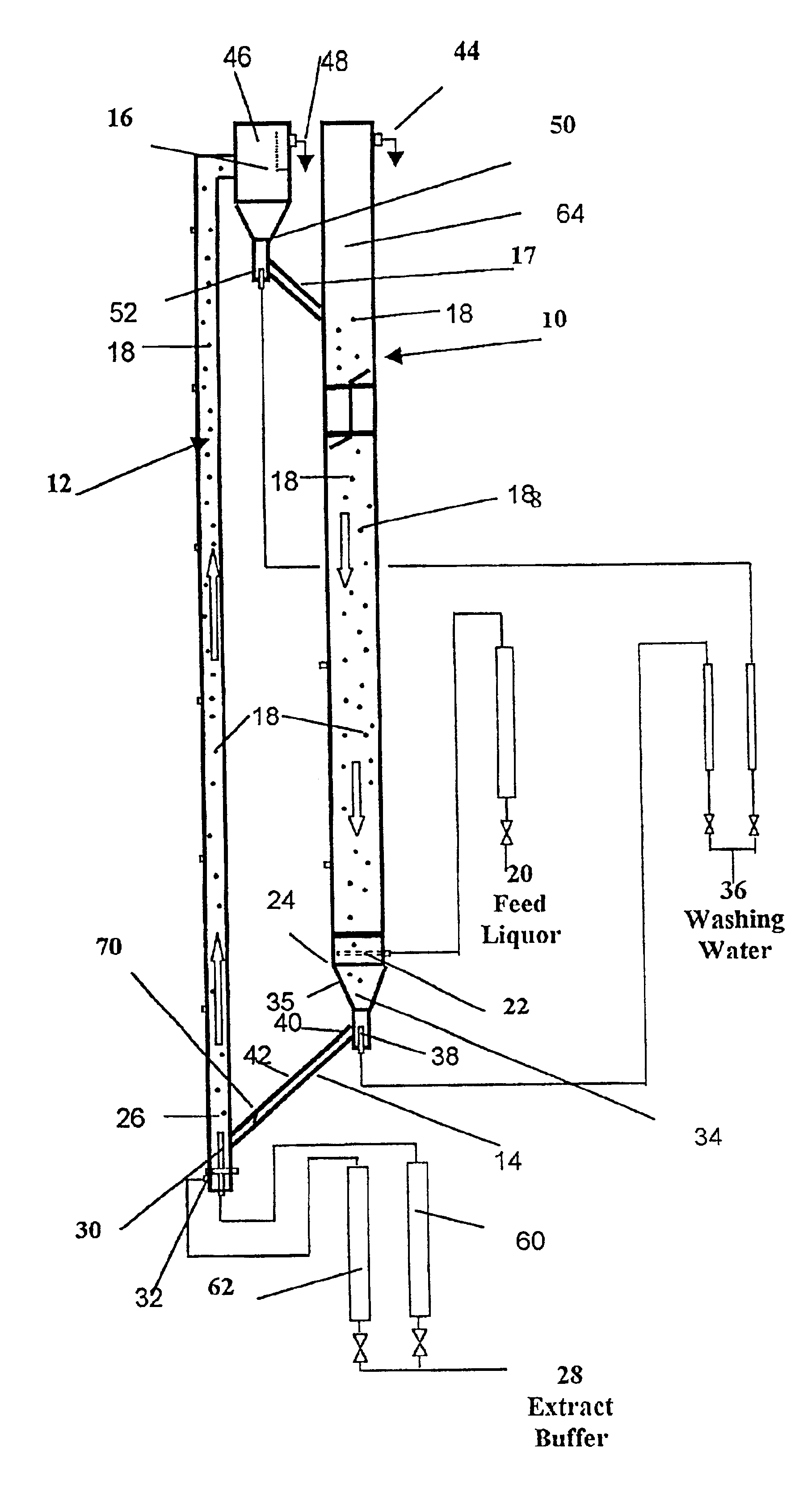
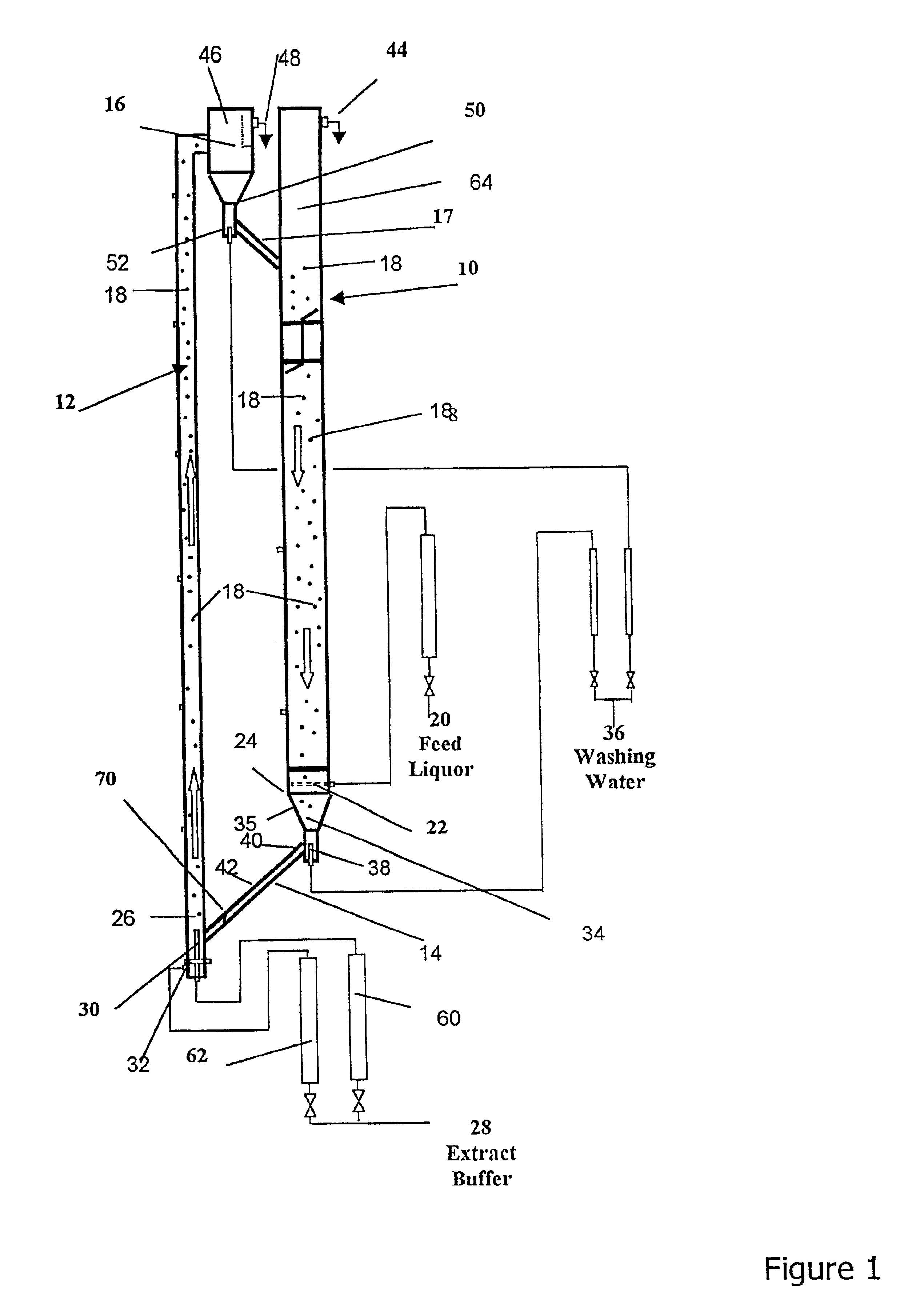
In arrangement as shown in FIG. 1, the second fluidized bed 12 is an acrylic column of I.D. 38.1 mm and 3 m in height. The distributor of the second fluidized bed 12 divides the incoming stream of extracting buffer into two substreams: the primary 60 and the auxiliary 62 streams. The primary stream 60 is introduced through a stainless steel pipe (I.D. 11 mm) (nozzle 30). It project 36 mm into the second fluidized bed column 12. Since the liquid velocity in the second fluidized bed is maintained in a range higher than the terminal velocity of the ion exchange paricles, the high liquid velocity enhances the contact efficiency and also the mass transfer rate between the liquid and the particles.

The top washing section 50 as above described comprises of the funnel bottom of the separator 46 and an acrylic pipe of 40 mm in diameter and 200 mm in height (pipe 17). The first fluidized bed is a Plexiglas column of I.D. 120 mm and 2.5 m in height. The particle entrance 17 on the first fluidi...


PUM

PropertyMeasurementUnit
Fractionaaaaaaaaaa
Fractionaaaaaaaaaa
Densityaaaaaaaaaa

Abstract

A continuous Liquid-Solids Circulating Fluidized Bed (LSCFB) preferably for use as an ion exchanger consists of two fluidized bed columns, a fluidized bed adsorber (downer) operating in conventional fluidized bed mode for adsorption of ions of interest and a fluidized bed riser for desorption of ions (operating as a riser fluidized bed) to provide regenerated particles. Ion exchange particles circulate continuously between the riser and the downer i.e. the particles that have adsorbed ions in the absorber pass from the adsorber (downer) to the desorber where they are regenerated and the so regenerated particles are return to the adsorber near the top of the adsorber column. The LSCFB can be used in processes for continuous recovery of the ions of interest.

Description

The present invention relates to a fluidized bed, more specifically, a liquid-solids circulating fluidized bed arrangement specially suited for ion exchange processes.BACKGROUND TO THE INVENTIONFluidized beds have been used for a number of different applications such as a gas-liquid, gas-liquid-solid contactors and to carry out a variety of different processes such as chemical reactions.Fluidized beds have found application in ion exchange process. For example Chase, H. A., "Purification of Proteins by Adsorption Chromatography in Expended Beds", TIBTECH 12, 296-303 (1994) describes a batch ion exchange process using a conventional fluidized bed for recovering proteins from whole fermentation broth with the presence of bacterial cells. It eliminates the difficult solids separation step and recovers the desired products directly from unclarified whole broth. This process is a batch process employing a conventional fluidized bed.Burns, M. A. and D. J. Graves, "Continuous Affinity Chro...

Claims


Application Information

Patent Timeline
IPC IPC(8): B01D15/02B01D15/04B01D24/36B01D24/00C02F1/42C02F3/30B01D15/18B01J47/10B01J49/00
CPCB01D15/02B01D15/1807B01J47/10B01J49/0026B01D2215/021B01J49/10
Inventor BASSI, AMARJEET SINGHZHU, JINGXULAN, QING DAOMARGARITIS, ARGYRIOSZHENG, YING
Owner UNIVERSITY OF WESTERN ONTARIO
Why Eureka
Try Eureka