Ultrasonic process for autocatalytic deposition of metal on microparticulate

a microparticulate, ultrasonic technology, applied in the direction of liquid/solution decomposition chemical coating, mechanical vibration separation, physical treatment, etc., can solve the problems of uncoated, clumping and flaking of silver, and "dead zones" where no metal application is possibl

Inactive Publication Date: 2004-04-27
THOMPSON G ALAN +1
View PDF8 Cites 26 Cited by
  • Summary
  • Abstract
  • Description
  • Claims
  • Application Information

AI Technical Summary

Benefits of technology

It is an object of the present invention to obviate or mitigate at least o...

Problems solved by technology

Conventional methods for metalizing, for example silverizing, often result in uneven coating, clumping and flaking of the silver.
Autocatalytic baths often result in "dead zones" where no metal application occurs.
Conventional methods for metalizing materials result in significant weight gain to a material, which is undesirable.
For ...

Method used


Image

  • Ultrasonic process for autocatalytic deposition of metal on microparticulate
  • Ultrasonic process for autocatalytic deposition of metal on microparticulate
  • Ultrasonic process for autocatalytic deposition of metal on microparticulate

Examples


example 1

Multi-Phased Shifted Ultrasonic Travelling Wave Ion Stimulation for Effective Autocatalytic Deposition of Silver onto Kevlar Microparticles at Resonance Frequency Vibration

The process according to the invention allows control and acceleration of the transfer rate of ionic silver onto sensitized microparticulate material in such a manner that permits uniform silver deposition, thus controlling the depositional thickness and eliminating problems resulting from clumping. This process also permits the effective de-gassing of the autocatalytic medium, eliminating problems associated with depositional voids. In turn, the thickness and quality of the silver deposition on the microparticulate controls the level of conductivity designated for the end product This process works two fold; such that the sensitized material is in motion perpendicular to the motion of the silver solution, which in turn is actively in motion by a second alternating phase shifted frequency at resonant vibration fre...

example 2

Polarized Application of Metallized Microparticulate onto a Surface

In order to apply metallized microparticulate onto a surface, any variety of methods may be employed.

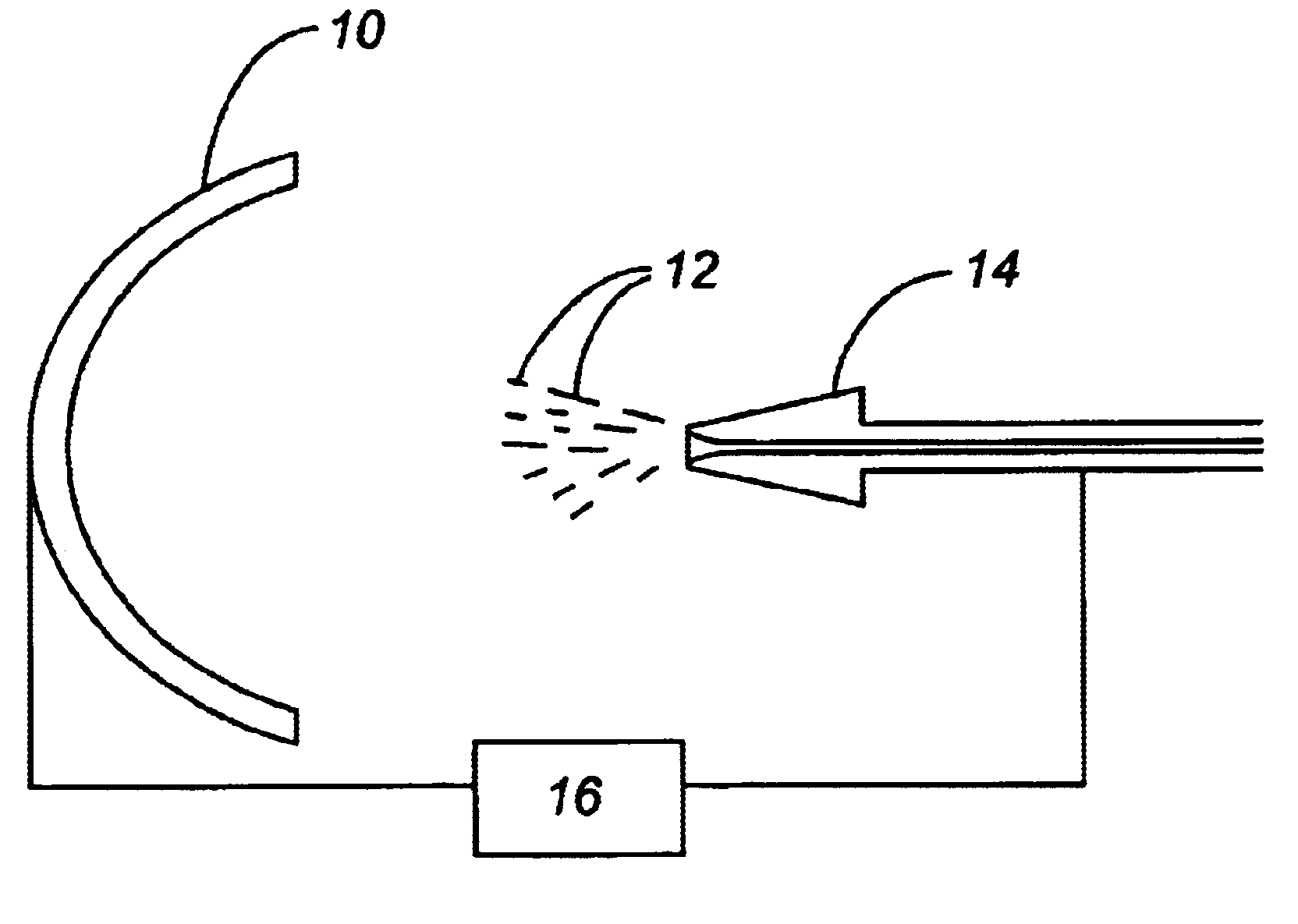
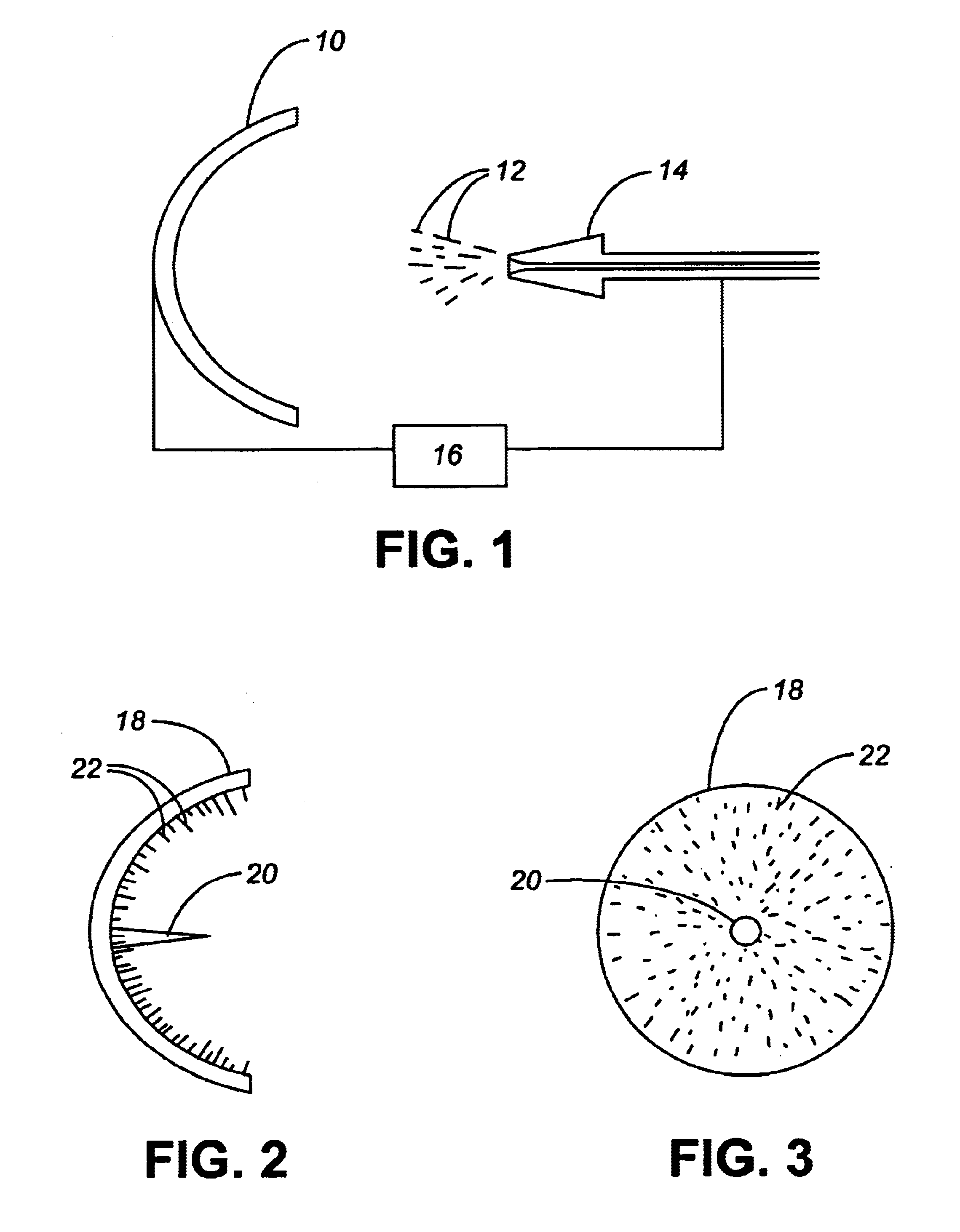
FIG. 1 illustrates application of silverized microparticulate onto a surface. In this example, a parabolic dish (10) provides an appropriate object target for application of metallized microparticulate in the form of silverized fibers (12) of varying lengths. A discharge nozzle (14) having an inert carrier gas (such as Ar, N.sub.2, He, etc.) travelling therethrough delivers the silverized fibers to the surface of the parabolic dish. The parabolic dish may optionally be pre-treated with a resin layer (such as an epoxy) to ensure that the fibers become lodged onto the surface of the dish. In order to orient the fibers end-on so as to be approximately perpendicular to the dish, an electrostatic charge generator (16) can be used to oppositely charge the dish (10) and the discharge nozzle (14). In this way, as the fibers a...

example 3

Combined Felted and Polarized Application of Metallized Microparticulate Onto a Surface

In order to apply metallized microparticulate onto a surface that required different types of metal coverage, any layered technique may be employed

FIG. 4 illustrates the front view of a flat surface (28) on which metallized microparticulate fibers (30) of varying sizes and lengths formed according to the methodology described herein, have been "felted". By "felted" it is meant applied in a random or unorganized fashion. This layer has not been polarized to effect an end-on orientation. In order to ensure adherence of the felted fibers to the surface, a resin layer may be included on the surface prior to application of the microparticulate. After application of the felted layer of metallized microfibers, a subsequent layer of polarized metalized microfibers is applied, using an apparatus such as that shown in FIG. 1.

FIG. 5 illustrates a flat surface (28) having a resin layer (32) coated thereon, fo...


PUM

PropertyMeasurementUnit
Thicknessaaaaaaaaaa
Electric chargeaaaaaaaaaa
Frequencyaaaaaaaaaa

Abstract

A process for depositing metal on microparticulate comprising immersing microparticulate in an autocatalytic plating bath comprising the metal; inducing ultrasonic vibration in the plating bath at a frequency corresponding to resonance frequency of the microparticulate; and inducing a turbulent vibration signal in the plating bath in a direction non-parallel to the ultrasonic vibration. This process results in the autocatalytic plating bath depositing the metal on the microparticulate with uniform thickness. The microparticulate can be spheres, flakes or microfibers, and can be made from a number of materials, such as synthetic polymers (nylon, Kevlar.TM., Zylon.TM., and aramid fibers) and biodegradable compounds. A method is disclosed for coating a surface with metallized microparticulate fibers with an orientation perpendicular to the surface.

Description

FIELD OF THE INVENTIONThe present invention relates generally to ionic metallic deposition onto material.BACKGROUND OF THE INVENTIONThere are many problems to be overcome in the metalizing of materials. Conventional methods for metalizing, for example silverizing, often result in uneven coating, clumping and flaking of the silver. Autocatalytic baths often result in "dead zones" where no metal application occurs.Metalized materials are fiequently used in the aeronautic industry. The military is aerospace industry has ongoing research programs to address the issues of impedance, resistance, RF resonance, RFI (radio frequency interference)--EMI (electromagnetic interference) shielding, conductivity levels, low observability applications, thermal signature reduction and transfer, attenuation of a variety of signal types, and infrared signature reduction requirements.Conventional methods for metalizing materials result in significant weight gain to a material, which is undesirable. For ...

Claims


Application Information

Patent Timeline
IPC IPC(8): C23C18/16D06M10/00D06M11/00D06M11/83D06M10/02D06M10/06
CPCC23C2/32C23C4/12C23C18/1635C23C18/1666C23C18/1669C23C18/31C23C24/00D06M10/02D06M10/06D06M11/83
Inventor THOMPSON, G. ALANMARX, DAVID E.
Owner THOMPSON G ALAN
Why Eureka
Try Eureka