Articles having improved residual stress profile characteristics produced by laser shock peening

a technology of residual stress and laser peening, which is applied in the direction of wind motors with parallel air flow, wind motors with perpendicular air flow, liquid fuel engine components, etc., can solve the problem of little attention to determining useful techniques that can provide, and achieve the effect of improving the penetration depth and better controlling the depth of residual stress

Inactive Publication Date: 2004-06-22
LSP TECH INC
View PDF5 Cites 28 Cited by
  • Summary
  • Abstract
  • Description
  • Claims
  • Application Information

AI Technical Summary

Benefits of technology

One advantage of the invention is that the laser shock peening process can increase the penetration depth of compressive residual stress formed below a laser shock peened surface beyond that available from a single pulse.
Another advantage of the invention is that the laser shock peening process can be used to tailor the sub-surface residual stress profile developed through the thickness of a thin section.
Another advantage of the invention is that asymmetry can be introduced into the stress distribution profile by simultaneously laser shock peening both sides of the thin section in the manner described herein, thereby allowing modification of the profile.
Another advantage of the invention is the availability of better control of the depth of the residual stress below the laser shock peened surface, and the intensity of the interaction of the shockwaves at mid-thickness of the thin section.

Problems solved by technology

However, little attention has been given to determining useful techniques that can provide desired shockwave groups and accompanying stress distribution profiles.

Method used


Image

  • Articles having improved residual stress profile characteristics produced by laser shock peening
  • Articles having improved residual stress profile characteristics produced by laser shock peening
  • Articles having improved residual stress profile characteristics produced by laser shock peening

Examples


first embodiment

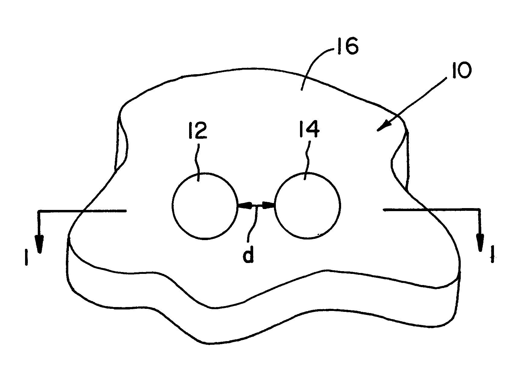
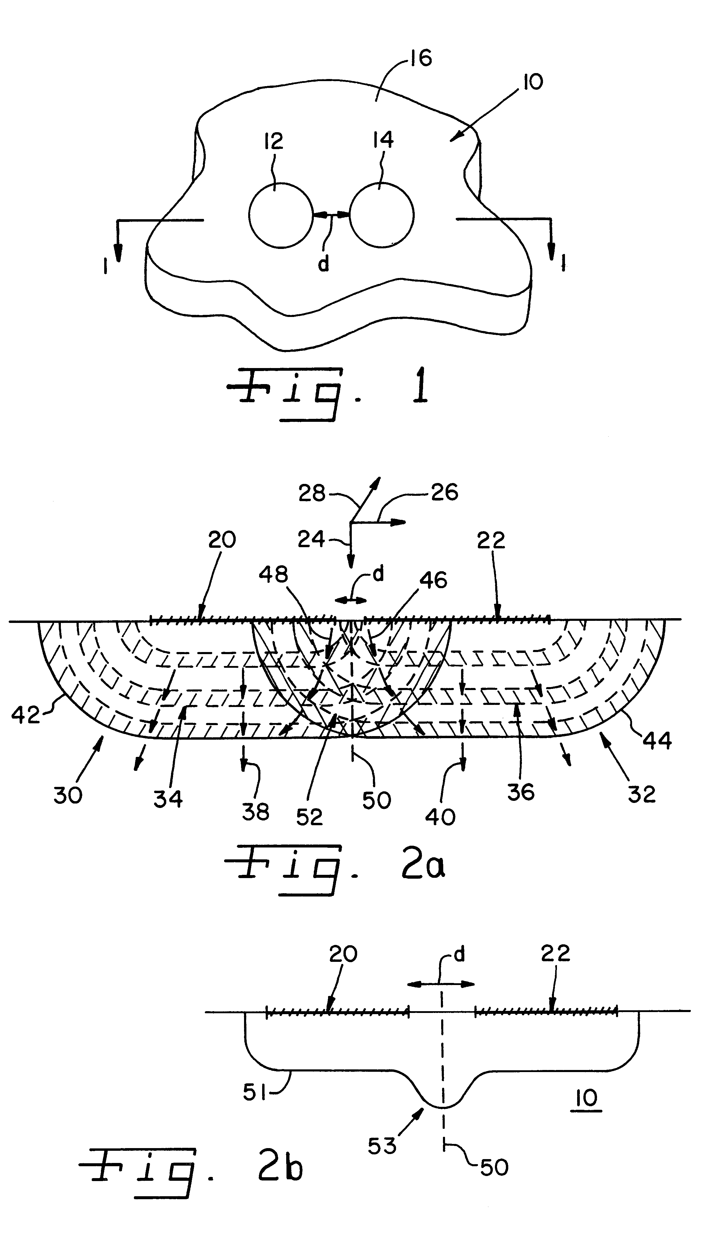
Turning now to the present invention, reference is first made to FIG. 1, which illustrates a representative laser beam spot configuration forming a set of laser shock peened surface areas on workpiece 10, according to the present invention. FIG. 2a is a cross-sectional planar view of workpiece 10 taken along lines 1--1 of FIG. 1. FIG. 2b is a similar cross-sectional planar view of workpiece 10, showing an illustrative stress contour line that is representative of the stress distribution profile which follows from the type of laser shock processing depicted in FIG. 1.

Workpiece 10 is irradiated with a set of laser beam spots 12 and 14 applied simultaneously to the surface 16 of workpiece 10 to form a respective set of adjacent non-overlapping laser shock peened surface areas coextensive with the dimensions of the laser beam spots. This treatment of workpiece 10 is conducted in accordance with a suitably configured laser shock processing operation. As shown, the laser beam spots 12, 14...

second embodiment

Reference is now made to FIGS. 8 and 9 to illustrate a laser shock processing operation, according to the present invention. As discussed further, this embodiment involves a dual-sided laser shock peening operation that forms fully opposing laser shock peened surfaces at opposing sides of a workpiece using an operating sequence that forms the relevant laser beam spots at different times.

For comparison purposes, reference is first made to FIG. 8A, which depicts the double-sided laser shock peening of a thin section using laser beams arriving at opposite sides of the workpiece at the same time. In particular, workpiece section 800 having opposite sides 802, 804 is simultaneously laser shock peened at sides 802, 804 to form laser shock peened surfaces 806 and 808, respectively.

As shown, shockwaves 810, 812 induced by laser shock peening propagate toward one another from respective laser shock peened surfaces 806, 808. Since the shockwaves 810, 812 were likewise created simultaneously, ...

third embodiment

Referring next to FIG. 10A, there is shown a cross-sectional view which depicts the double-sided, simultaneous laser shock peening of a thin section using laser beams having different pulse lengths, according to the present invention.

Illustrative workpiece 900 includes sides 902 and 904 disposed generally opposite one another and a mid-thickness plane 914. The opposing sides 902 and 904 are simultaneously laser shock peened with laser beams having different pulse lengths to form opposing laser shock peened surfaces 906 and 908, respectively. As shown, the laser shock peened surfaces 906 and 908 are respectively irradiated with representative laser beams 910 and 912, where the pulse length of laser beam 910 is longer than the pulse length of laser beam 912.

It is preferable that the laser shock peened surfaces 906, 908 be shaped and dimensioned identically. This requires, for example, the use of identically sized laser beam spots. Additionally, it is preferable that the laser shock pe...


PUM

PropertyMeasurementUnit
timeaaaaaaaaaa
timeaaaaaaaaaa
thickaaaaaaaaaa

Abstract

Articles produced by laser shock processing exhibit various compressive residual stress distribution profiles. A gas turbine engine airfoil includes an asymmetrical stress profile formed through the thickness of its thin section. The articles include plural laser shock peened surfaces and plural regions having deep compressive residual stresses imparted by laser shock peening extending into the article from the laser peened surfaces. One article includes at least one set of simultaneously formed, adjacent non-overlapping laser shock peened surfaces. Another article includes at least one set of opposing laser shock peened surfaces formed at different times at opposite sides of the article. Another article includes at least one set of opposing laser shock peened surfaces formed simultaneously at opposite sides of the article using laser beams having different pulse lengths. Another article includes at least one set of laterally offset laser shock peened surfaces simultaneously formed at opposite sides of the article.

Description

BACKGROUND OF THE INVENTION1. Field of the InventionThe present invention relates generally to articles manufactured by laser shock peening techniques, and, more particularly, to various article constructions exhibiting enhanced compressive residual stress characteristics induced by laser shock peening, such as selectively configured compressive residual stress distribution profiles having a desired asymmetry appearing within processed workpieces or objects, such as an airfoil.2. Description of the Related ArtLaser shock processing has found use in applications involving the enhancement of certain structural features such as the leading and trailing edges of turbine engine compressor or other airfoils. Various strategies have focused upon finding adequate laser beam spot patterns to process the airfoil. However, little attention has been given to determining useful techniques that can provide desired shockwave groups and accompanying stress distribution profiles.In a typical applica...

Claims


Application Information

Patent Timeline
Patent Type & Authority Patents(United States)
IPC IPC(8): C21D10/00F01D5/28
CPCC21D10/005F01D5/286C21D2221/00Y02T50/672Y02T50/60
Inventor CLAUER, ALLAN H.LAHRMAN, DAVID F.DULANEY, JEFF L.TOLLER, STEVE M.
Owner LSP TECH INC
Why Eureka
Try Eureka