Acoustic sounding

a technology of acoustic sounding and sound waves, applied in the field of acoustic sounding, can solve the problems of not being able to provide the discrimination required in demanding situations, and achieve the effect of enhancing the effect of both loudspeaker and microphon

Inactive Publication Date: 2004-06-29
WINDBIDCO
View PDF11 Cites 24 Cited by
  • Summary
  • Abstract
  • Description
  • Claims
  • Application Information

AI Technical Summary

Benefits of technology

The present invention involves an acoustic sounding system wherein the component tones in a transmitted chirp are mixed, differenced, correlated or otherwise compared with the component tones in an echo chirp resulting from the reflection, refraction and / or scattering of the transmitted chirp. In this way, chirp transit times (and therefore the location of reflecting or refracting discontinuities in range) can be indicated as a frequency difference between the transmitted and the received chirps at any given instant. Furthermore, phase jitter or variation in an echo tone can be detected and displayed to indicate variation in velocity of the reflecting or refracting discontinuity with respect to the transmitter and / or receiver. The transmitted acoustic chirp can be generated by feeding a loudspeaker with an electrical input signal from the sound card of a computer (for example), while the echo chirp can be detected using a microphone that generates an electrical echo signal. Though the effectiveness of both loudspeaker and microphone can be enhanced by using suitable reflector dishes, the acoustic power required in the pulse is tiny in comparison to that required for the single-tone pulse of the art.
Comparison of the input and echo signals off-line--ie, not in real time--offers the advantage that the range of distances from which echoes are generated can be selected. Either or both the input and the echo signals can be recorded (before or after digitization and transformation) and then jointly played back with the desired time-offset to effect their comparison. For example, if signal processing considerations limit the chirp length to 15 s so that the maximum height at which TILs can be reliably detected in real time is, say, around 5000', the input signal can be delayed by, say, 15 s after the transmission of the acoustic chirp, so that TILs in the range of 5000 to 10000' can be detected using real-time echo signals by comparing the delayed signal with the echo signals arriving between 15 and 30 s after the start of the acoustic chirp.
As indicated above, a convenient method of generating the chirp is to feed appropriate software (eg, MIDI commands) to a PC sound card so that the desired tone sequence can be generated upon command if a linear chirp is to be used, this technique allows the tone increments to be sufficiently small to create the effect of a continuous phase-shift--or smooth glissando--from beginning to end of the chirp. This input signal can be stored in a sound (wave) file in the PC and used generate repeated chirps at any desired time interval and, as already indicated, this input signal can be transmitted to a mixer for comparison with the echo signal at any desired time. Of course, acoustic chirps should not be transmitted so frequently that echoes from multiple chirps are received at the same time. If desired, a Fourier transformed input signal may be stored in the PC so that it can be fed to the comparator at the appropriate time for mixing with the transformed echo signal. This technique can reduce the real-time processing burden.
It will be appreciated that there will necessarily be direct transmission of the signal pulse from transmitter to receiver via the shortest route, as well as some indirect reflections from terrestrial objects. These `direct` pulses may overlap the desired echoes in time at the receiver and degrade echo detection and processing. The direct pulse can be attenuated by acoustically isolating the transmitter and receiver, but this is often difficult or inconvenient. It can be subtracted from the echo chirp using known DSP techniques but, if the overlap of the direct and echo chirps is not great for the echoes of most interest, processing in the Fourier or frequency domain can effectively remove or discount most direct chirps. If the direct signals are not removed, the resulting amplitude-time display will show early high-amplitude returns that can be readily ignored in most cases.
The use of chirped acoustic sounders aligned with and cross-runway such that the chirped pulses are directed at a low elevation allows windshear and CAT in the vicinity of a runway to be identified. Preferably, mirrored transmitter and receiver sets are used in each direction so that pulses can be transmitted first in one direction and then in the other. The height of the windshear or CAT can be estimated by the time delay between transmission and reception of the reflected or refracted pulses, while the velocity of the associated body of air in the pulse-beam direction can be estimated by comparing the differential time shifting of the `up` and `down` pulses. The component time-delay measurements that allow the differential comparison can each be obtained using the techniques indicated above, yielding a highly accurate measurement of wind velocity or turbulence at any desired height within range. In general, chirp transit-time measurements conducted in this way will be more accurate than Doppler-based measurements.
As also mentioned above, the chirped acoustic pulse techniques offer substantial benefits in the characterisation of concert hall acoustics, though the chirp duration will generally be shorter and the chirp bandwidth higher than for atmospheric sounding. This allows highly precise measurement of the length of the principal multiple paths between a chirped pulse transmitter at a given location to a given receiver location, which then allows computation of multi-path interference for those locations over the range of audible tones. Such measurements and computations then provide most valuable inputs into the correction or optimisation of an existing concert hall.

Problems solved by technology

While the comparison can be done with analog systems using known mixer circuits, they may not be able to provide the discrimination required in demanding situations.

Method used


Image

  • Acoustic sounding
  • Acoustic sounding
  • Acoustic sounding

Examples


Embodiment Construction

Having portrayed the nature of the present invention, particular examples will now be described with reference to the accompanying drawings. However, those skilled in the art will appreciate that many variations and modifications can be made to the chosen examples without departing from the scope of the invention as outlined above. In the accompanying drawings:

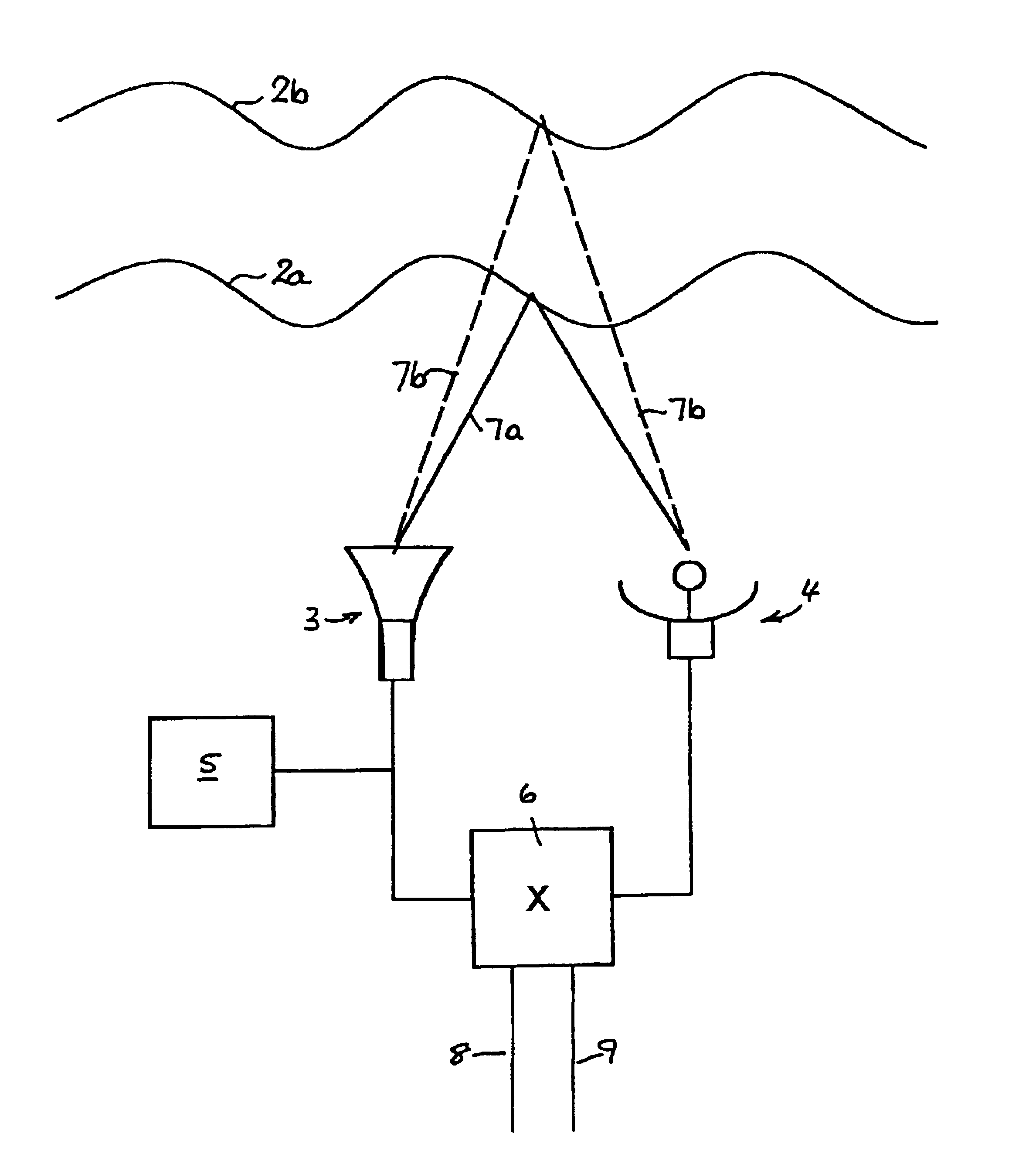
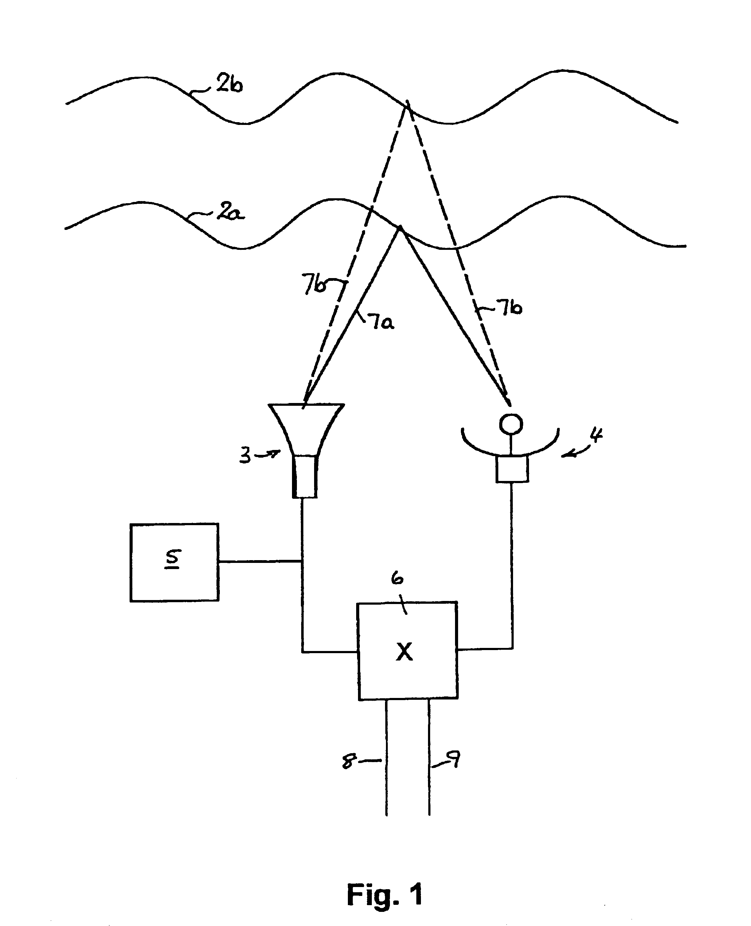
FIG. 1 is a simple block diagram showing the principal components of an acoustic sounder for use in detecting TILs below 3000'.

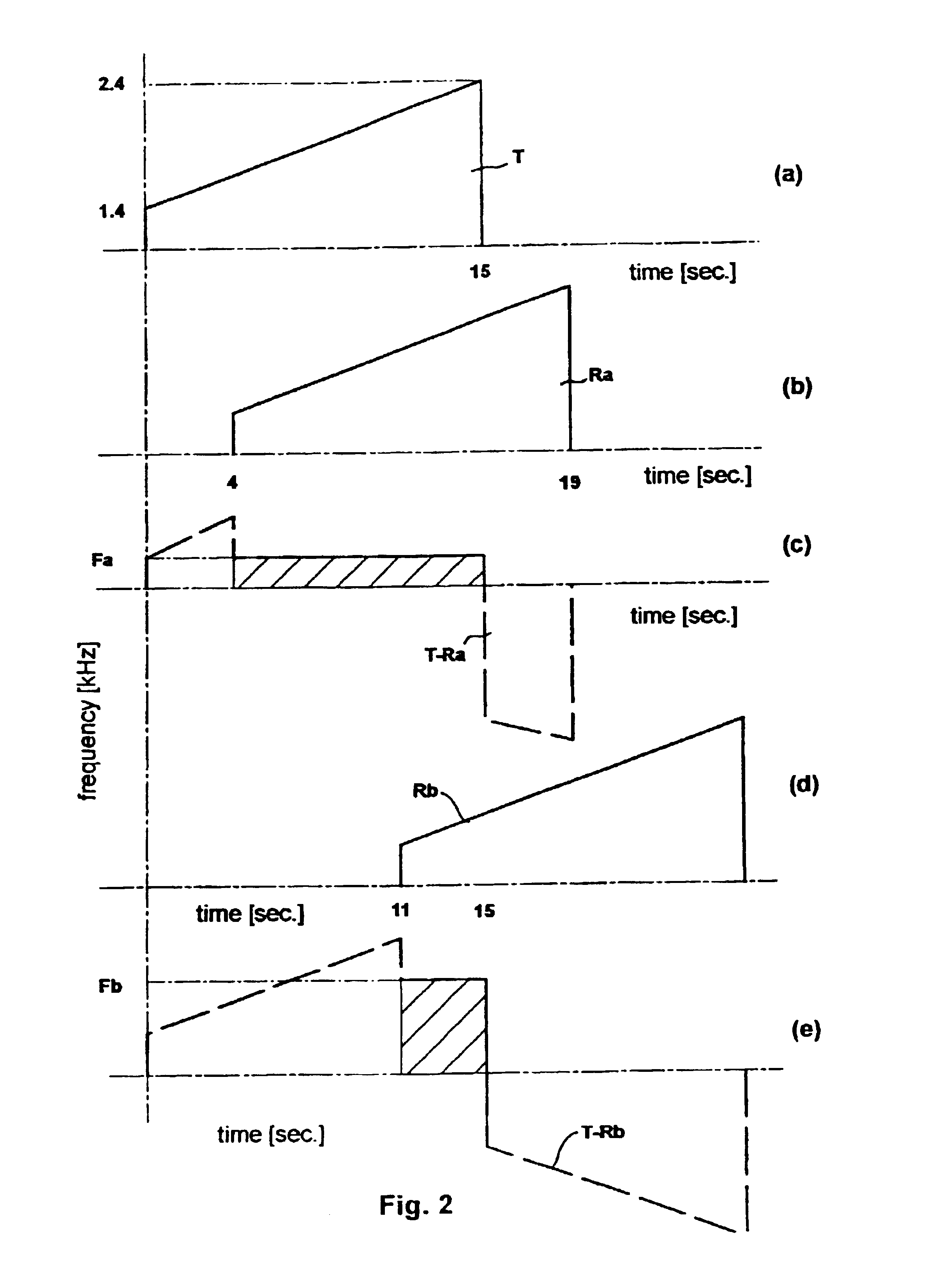
FIG. 2 is a set of graphs showing a simple process whereby a transmitted chirp (a) can be combined with echo chirps (b) and (d) to generate useful outputs (c) and (e).

FIG. 3 is a more detailed block diagram of a sounding system employing Fourier domain comparison or mixing.

FIG. 4 is a flow-chart depicting a procedure for Fourier-domain processing of the transmitted and echo chirps in the system of FIG. 3.

FIG. 5 is a graph, derived from radiosonde measurements, showing variation of air temperature (Te) ...


PUM

PropertyMeasurementUnit
audio frequencyaaaaaaaaaa
speedaaaaaaaaaa
altitudeaaaaaaaaaa

Abstract

Methods and apparatus for atmospheric sounding using acoustic chirps are disclosed, the transmitted and echo chirps being compared in a mixer that yields frequency sums and differences. Preferably, the mixing is performed as a complex multiplication in the Fourier domain. In one system (1) a signal generator (5) such as a PC sound card drives a loudspeaker (3) that serves as a transmitter and echo pulses are detedcted by a microphone (4) that serves as a receiver. Chirps transmitted by the loudspeaker (3) travel by different paths (7a and 7b) due to reflection from TILS or thermal inversion layers (2a and 2b) at different altitudes. The transmitted and echo chirp signals are compared in a mixer (6) from which various outputs (8 and 9) can be generated. One output (8) might be the magnitude of the difference between the transmitted and echo chirp tones, instant by instant, which is indicative of the altitudes of the respective TILs. The other output (9) might be the phase shift in an echo tone with transit time, which is indicative of vertical wind velocity at different altitudes. Such sounding methods and apparatus are useful for weather research, prediction of plume dispersal and the design of microwave links to minimize multipath fading.

Description

This invention relates to the use of acoustic pulses for atmospheric sounding or probing. It is particularly useful in measuring the height and other characteristics of thermal inversion layers [TILs] and other discontinuities in the lower atmosphere. TILs can affect radio transmission as well the transport and / or dissipation of pollutants, while other discontinuities such as windshear and clear-air turbulence near airports can affect aircraft safety.Another technical field to which this invention may be applied is the investigation and characterization of the acoustics of buildings or the built environment.In this specification "sound" will be used as a verb meaning to acoustically probe or explore, and "sounding" will be used as a noun to indicate the result of acoustic probing or exploration. If it is necessary to employ "sound" to mean an auditory sensation or the vibrations capable of causing such sensations or, indeed, to mean the generation of such vibrations (as in `to make ...

Claims


Application Information

Patent Timeline
Patent Type & Authority Patents(United States)
IPC IPC(8): G01S15/88G01S15/00G01S15/58G01S15/34G01S15/87
CPCG01S15/885G01S15/34G01S15/588G01S15/87G01S15/003G01W2001/003
Inventor MARTIN, ANDREW LOUIS
Owner WINDBIDCO
Why Eureka
Try Eureka