
Method of manufacturing a thermostructural composite material bowl, in particular for an installation that produces silicon single crystals

a composite material and manufacturing method technology, applied in the direction of polycrystalline material growth, crystal growth process, coating, etc., can solve the problems of increasing the mass of liquid, increasing the cost of the material, and fragile pieces of graphite used as bowls. achieve the effect of low cos

Inactive Publication Date: 2004-08-31
SNECMA MOTEURS SA
View PDF10 Cites 10 Cited by
  • Summary
  • Abstract
  • Description
  • Claims
  • Application Information

AI Technical Summary

Benefits of technology

An object of the invention is to propose a method of manufacturing a bowl of thermostructural composite material that makes it possible to overcome the above difficulties, while remaining simple and low in cost.
Such purification treatment can be performed on the consolidated bowl preform. The heat treatment then also contributes to avoiding dimensional variations during the subsequent manufacturing processes. Providing the plug closing the bottom of the bowl has also been subjected to purification treatment, performing purification after chemical vapor infiltration need not be necessary.

Problems solved by technology

The pieces of graphite used as bowls are fragile.
This safety problem becomes more critical with the increasing size of the silicon ingots that are drawn, and thus with the increasing mass of the liquid silicon.
Furthermore, graphite bowls are generally of short lifetime while being thick and thus bulky.
For pieces that are of relatively complex shape, for example bowl shaped, a particular difficulty lies in making a fiber preform having the right shape.
Another difficulty lies in obtaining densification in a manner that is reasonably simple and fast, in particular for bowls of large dimensions.
Unfortunately, in the semiconductor industry, there exists a need for silicon ingots of ever greater diameter, thus requiring crucibles and support bowls to be provided that are of corresponding dimensions.

Method used


Image

  • Method of manufacturing a thermostructural composite material bowl, in particular for an installation that produces silicon single crystals
  • Method of manufacturing a thermostructural composite material bowl, in particular for an installation that produces silicon single crystals
  • Method of manufacturing a thermostructural composite material bowl, in particular for an installation that produces silicon single crystals

Examples


Embodiment Construction

As already mentioned, the field to which the invention applies is more particularly that of making bowls of thermostructural composite material for supporting crucibles in installations that produce single crystal silicon ingots.

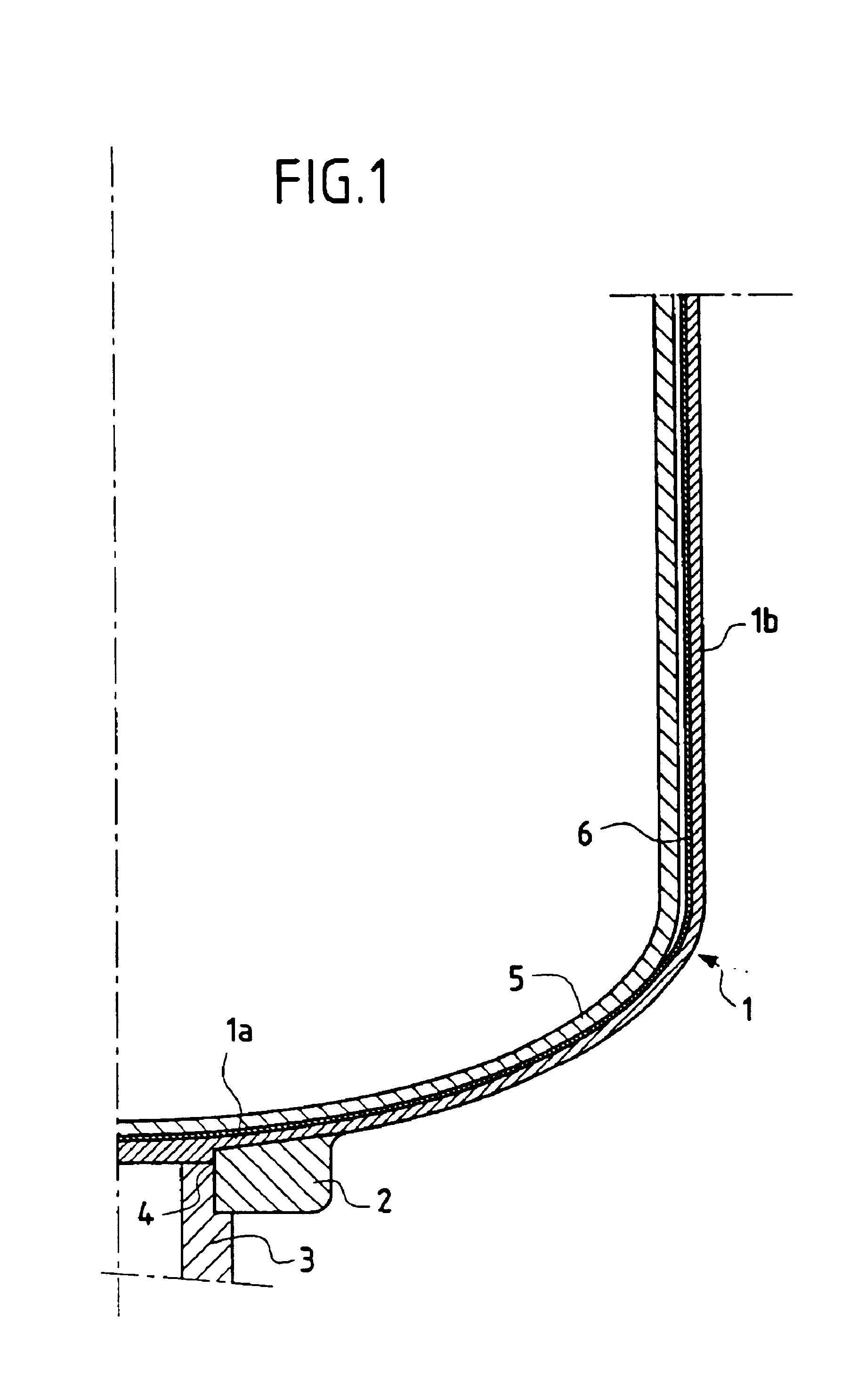
Highly diagrammatic FIG. 1 shows such a bowl of composite material, e.g. C / C composite material supporting a crucible 5 which is usually made of quartz. The bowl 1 stands on an annular support formed with a ring 2 mounted at the end of a shaft 3 having a setback 4 therein. The bowl has a bottom portion la and a surround portion 1b, part of which is substantially cylindrical and is connected to the bottom portion via a region of rounded profile. The bottom portion of the bowl 1 is machined so as to form a centering bearing surface corresponding to the setback 4 and a support surface on the ring 2.

After the crucible has been filled with silicon, the assembly is placed in a furnace and the temperature in the furnace is raised to a value which is high enough to ...


PUM

PropertyMeasurementUnit
Temperatureaaaaaaaaaa
Electrical resistanceaaaaaaaaaa
Shapeaaaaaaaaaa

Abstract

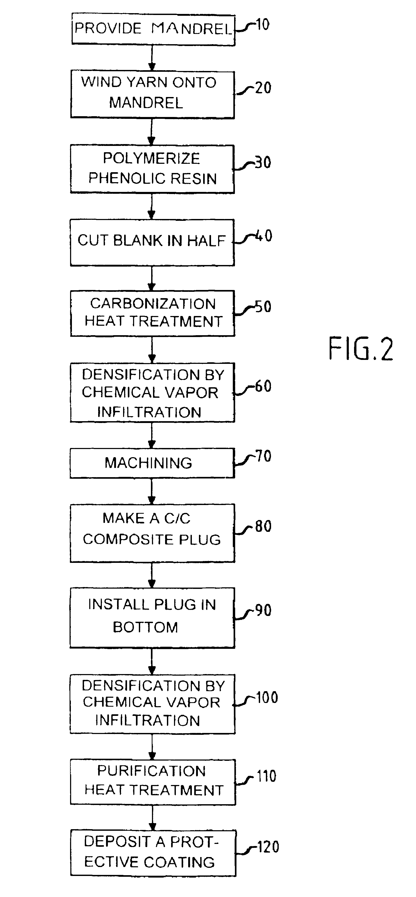
A composite material bowl 36 comprising fiber reinforcement densified by a matrix is made by winding a yarn on a preform 28 having an axial passage 30 through its bottom, densifying the preform by chemical vapor infiltration, and closing the passage by a plug 34. Prior to densification, the preform can be consolidated. A final chemical vapor infiltration step can be performed after the plug has been put into place.

Description

The invention relates to thermostructural composite material bowls. A field of application of the invention is more particularly manufacturing bowls for receiving crucibles containing molten metal, such as silicon.The term "thermostructural composite material" is used to mean a material comprising fiber reinforcement made of refractory fibers, e.g. carbon fibers or ceramic fibers, and densified by a refractory matrix, e.g. of carbon or of ceramics. Carbon / carbon (C / C) composite materials and ceramic matrix composite (CMC) materials are examples of thermostructural composite materials.A well-known method of producing silicon single crystals in particular for manufacturing semiconductor products consists in melting silicon in a crucible, in putting a crystal germ having a desired crystal arrangement into contact with the bath of liquid silicon, so as to initiate solidification of the silicon contained in the crucible with the desired crystal arrangement, and in mechanically withdrawin...

Claims


Application Information

Patent Timeline
IPC IPC(8): C04B35/80C04B35/83C23C16/04C30B15/10C30B35/00D04H3/07D04H13/00D04H3/02C04B41/87C04B35/52C04B35/84C30B29/06D04H3/002
CPCC04B35/806C04B35/83C23C16/045C30B15/10C30B35/002D04H3/002D04H3/07D04H13/00C04B35/565C04B35/80C04B2235/48C04B2235/5248C04B2235/5256C04B2235/6028C04B2235/612C04B2235/614C04B2235/616C04B2235/94
Inventor GEORGES, JEAN-MICHELBENETHUILIERE, DANIELPHILIPPE, ERIC
Owner SNECMA MOTEURS SA
Learn More