Magnetic head comprising a multilayer magnetoresistive device and a yoke for introducing magnetic flux from a medium to the magnetoresistive device

a multi-layer magnetoresistive device and magnetoresistive device technology, applied in the field of magnet head, can solve the problems of increasing the device resistance and the compactness of the device, and achieve the effect of improving the magnetic field

Inactive Publication Date: 2004-08-31
PANASONIC CORP
View PDF15 Cites 13 Cited by
  • Summary
  • Abstract
  • Description
  • Claims
  • Application Information

AI Technical Summary

Benefits of technology

It is an object of the present invention to provide a magnetic head having a structure suitable for a magnetoresistive device (magnetoresistive effect device) in which current flows perpendicularly to the film plane, such as a TMR device. It is another object of the present invention to provide a magnetic head having improved characteristics that can be achieved by improving the magnetoresistive device in which current flows perpendicularly to the film plane.
Furthermore, for processing the magnetic head, physical or chemical etching such as ion milling, RIE, EB, FIB, I / M or the like used in a regular semiconductor process can be used. If smoothing is required in the microfabrication, a CMP method or a photolithography using the line width in accordance with the necessary microfabrication can be used. When forming films for the device, if cluster-ion beam etching is used to smooth the surface of the formed film, the MR can be improved.

Problems solved by technology

In the magnetoresistive device in which current flows in a direction perpendicular to a film plane, unlike a device in which current flows along an inplane direction, an increase of the device resistance involved in achieving compactness of the device may deteriorate the characteristics of the head easily.

Method used


Image

  • Magnetic head comprising a multilayer magnetoresistive device and a yoke for introducing magnetic flux from a medium to the magnetoresistive device
  • Magnetic head comprising a multilayer magnetoresistive device and a yoke for introducing magnetic flux from a medium to the magnetoresistive device
  • Magnetic head comprising a multilayer magnetoresistive device and a yoke for introducing magnetic flux from a medium to the magnetoresistive device

Examples


example 1

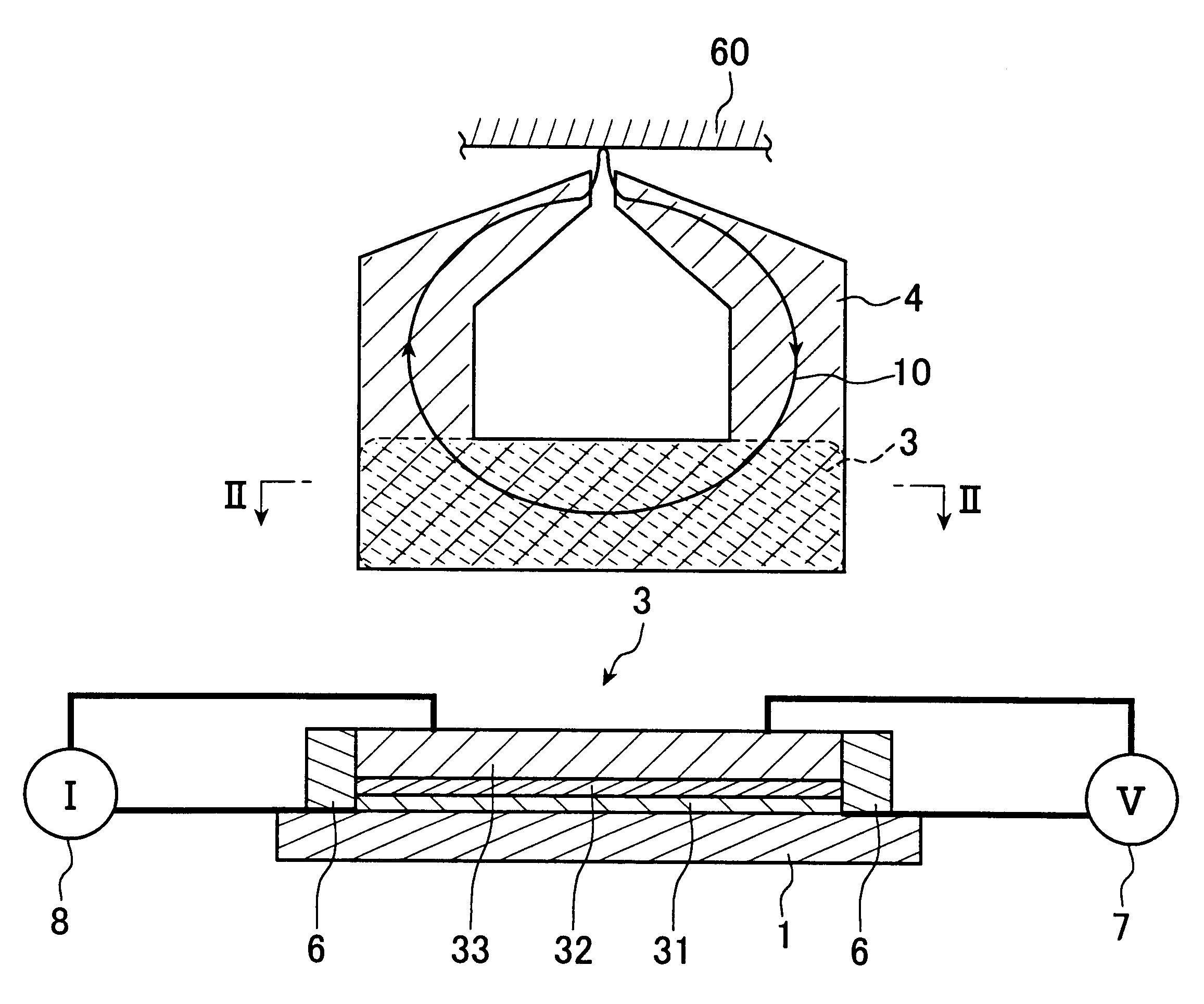
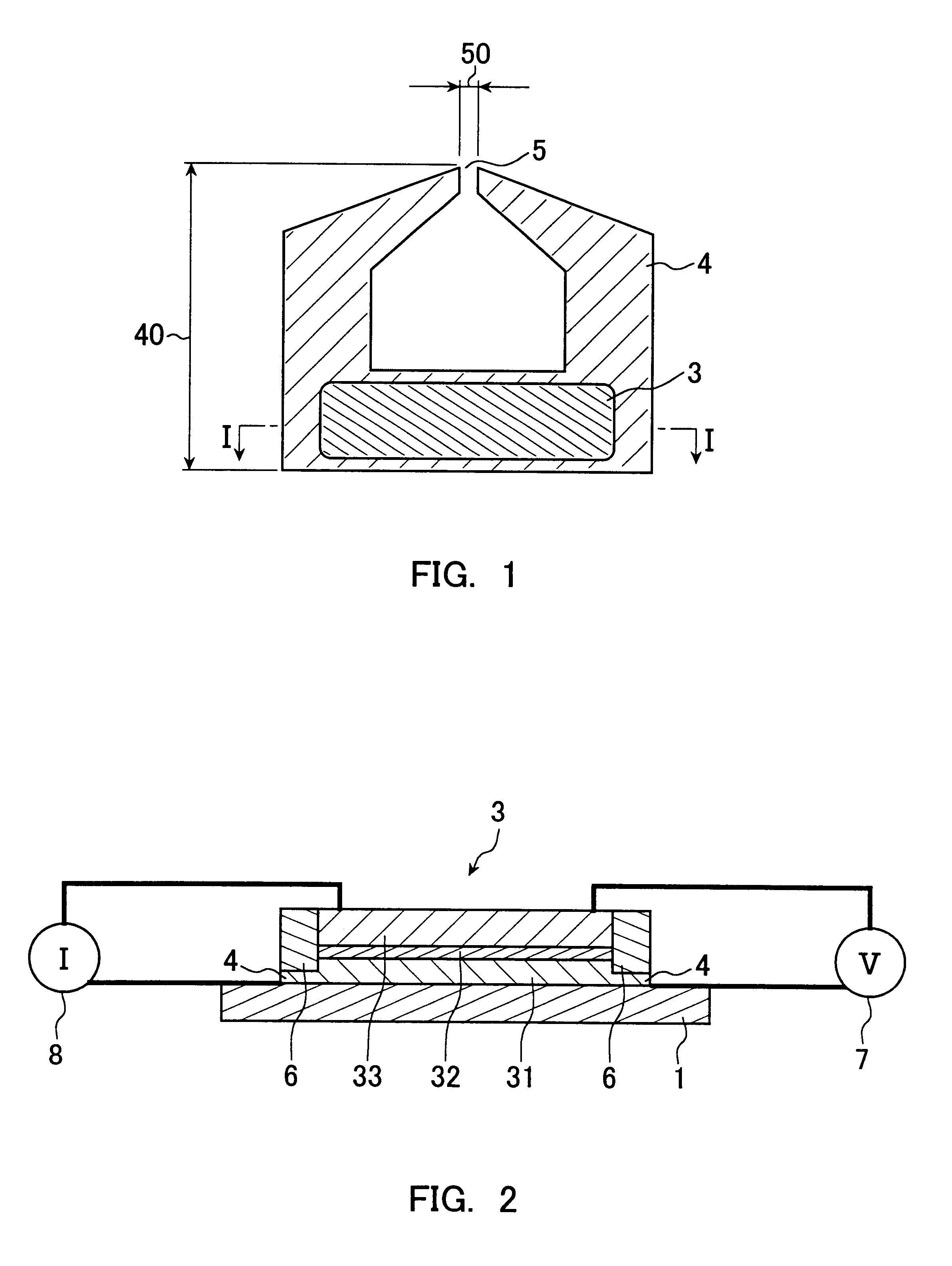
A magnetic head is produced having the same structure as that shown in FIGS. 1 and 2. In this magnetic head, a magnetoresistive device is formed on a yoke.

Using RF magnetron sputtering, Ta(3) / Cu(100) / Ta(3) / NiFe (20) / Al(0.4) were formed in this order on an AlTiC plate as a substrate. The Cu layer is a lower electrode. The NiFe layer is a first magnetic layer as a free layer. The Ta layer is an underlying layer. The values in parentheses indicate the thickness (unit nm; this applies to the following).

Then, after the Al was oxidized in an oxygen atmosphere of 200 Torr for 1 minute, an Al (0.3) film was formed thereon. Furthermore, this Al was oxidized in an oxygen atmosphere with 200 Torr for 1 minute. Thus, an Al oxide film (alumina) was formed as the non-magnetic layer.

Then, Co.sub.90 Fe.sub.10 (3) / Ru(0.7) / Co.sub.90 Fe.sub.10 (4) / PtMn(30) / Ta(3) were formed into films in this order. The Co.sub.90 Fe.sub.10 (3) / Ru(0.7) / Co.sub.90 Fe.sub.10 (4) / PtMn(30) was the second magnetic layer as t...

example 2

As in Example 1, a magnetic head having the same structure as shown in FIGS. 1 and 2 was produced. In this example, the MR ratio was examined with the ratio of the device cross-section area to the yoke area kept constant at 30% or more and the yoke height varied, in the same manner as in Example 1.

As shown in Table 4, the results indicate that when the ratio of the device cross-section area to the yoke area is 30% or more and the yoke height is 10 .mu.m or less, more excellent reading characteristics can be obtained.

example 3

A magnetic head having the same structure as shown in FIGS. 9 and 10 was produced. In this magnetic head, the yoke is formed on the magnetoresistive device. Hereinafter, a production method will be described with reference to FIG. 11.

First, Ta(3) / Cu(500) / Ta(3) / PtMn(30) / CoFe(3) / Ru(0.7) / CoFe(3) / Al(0.4;1 min. oxidation with pure oxygen with 260 Torr) / Al(0.3;1 min. oxidation with pure oxygen with 260 Torr) / CoFe(3) / NiFe(30) / Ta(3) were formed in this order on an AlTiC plate as a substrate 1, and annealed at 260.degree. C. for 2 hours (FIG. 11A). The Cu layer was a lower electrode, and PtMn(30) / CoFe(3) / Ru(0.7) / CoFe(3) was the first magnetic layer 31 as the pinned layer. The Al oxide film was the non-magnetic layer 32. The CoFe(3) / NiFe(30) was the second magnetic layer 33 as the free layer.

When a voltage was applied to these layers from a cross electrode of 3.times.3 .mu.m.sup.2, the MR curve shown in FIG. 26 was obtained, and the junction resistance was 25 .OMEGA..multidot..mu.m.sup.2.

Then...


PUM

PropertyMeasurementUnit
heightaaaaaaaaaa
areaaaaaaaaaaa
thicknessaaaaaaaaaa

Abstract

The present invention provides a magnetic head having improved characteristics, using a magnetoresistive device in which current flows across the film plane such as a TMR device. In a first magnetic head of the present invention, when the area of a non-magnetic layer is defined as a device cross-section area, and the area of a yoke is defined as a yoke area, viewed along the direction perpendicular to the surface of the substrate over which the yoke and the magnetoresistive device are formed, then the device cross-section area is not less than 30% of the yoke area, so that a resistance increase of the device cross-section area is suppressed. In a second magnetic head of the present invention, a magnetoresistive device is formed on a substrate, and a yoke is provided above a non-magnetic layer constituting the device. In a third magnetic head of the present invention, the free layer of the magnetoresistive device includes at least two magnetic films and at least one non-magnetic film that are laminated alternately, and the thickness of the non-magnetic layer is not less than 2 nm and not more than 10 nm, and magnetostatic coupling is dominant. In a fourth magnetic head of the present invention, a magnetic gap is provided adjacent to the magnetoresistive device and the magnetic films are coupled antiferromagnetically.

Description

The present invention relates to magnetic heads useful as reading heads for magnetic media such as magnetic disks, magneto-optical disks and magnetic tapes. In particular, the present invention relates to magnetic heads using magnetoresistive devices in which current flows perpendicularly to the film plane via a non-magnetic layer, such as a magnetoresistive device using a tunneling magnetoresistive effect (TMR device) and a magnetoresistive device using a giant magnetoresistive effect of the current perpendicular to the plane type (CPPGMR device).In order to deal with increasing magnetic recording densities, spin-valve type GMR devices are beginning to be put into use. The principle of the spin-valve type GMR devices is explained based on changes in the mean free path of electrons traveling in the direction along the film plane (inplane direction), depending on the angle formed by the magnetization directions of the free layer and the pinned (fixed) layer. The spin-valve type GMR d...

Claims


Application Information

Patent Timeline
Patent Type & Authority Patents(United States)
IPC IPC(8): G11B5/39G11B5/10G11B5/012G11B5/11G11B5/40
CPCB82Y10/00B82Y25/00G11B5/3903G11B5/3909G11B5/3916G11B5/3925G11B5/398G11B5/012G11B5/11G11B5/40G11B2005/3996
Inventor HIRAMOTO, MASAYOSHIMATSUKAWA, NOZOMUODAGAWA, AKIHIROIIJIMA, KENJISAKAKIMA, HIROSHI
Owner PANASONIC CORP
Why Eureka
Try Eureka