Rapidly-convertible roadable aircraft

a technology of roadable aircraft and convertible wings, which is applied in the direction of canard-type aircraft, transportation and packaging, efficient propulsion technologies, etc., can solve the problems of failure to achieve practical success, large wing surface area, and additional heavy weight of flying cars, so as to reduce drag, reduce wing exposure, and small hangar space

Inactive Publication Date: 2004-09-07
EINSTEIN HARRY
View PDF7 Cites 43 Cited by
  • Summary
  • Abstract
  • Description
  • Claims
  • Application Information

AI Technical Summary

Benefits of technology

include simplicity of construction, reduced drag due to 3 lifting surfaces rather than the conventional one. A non-roadable version of this aircraft would have a small hangar space requirement of approximately 1 / 4 of that of a comparative size light aircraft, safer outdoor (airfield) storage, very minimal wing exposure provides high resistance to wind damage. A non-roadable aircraft version can be towed on its own wheels or trailered, which aircraft can be stored and serviced at one's home in a one car garage. The design indicates decreased drag due to the `pusher` design. The wing storage systems add negligible weight and the small wing spans permits a lighter structure, the forces on the wings having a shorter moment, approximately half of that of a conventional comparative aircraft.

Problems solved by technology

There have been some successful flights of "flying cars" and even some that achieved certification, but none have proven practical.
The failures in achieving practical success were due, in part, to the designs which were attempts to add the flying components to existing or special cars.
The additional heavy weight of the flying car required large wing surfaces and high power.
Flying to an airport other then the departing airport still leaves one without readily available ground transportation at most airports servicing light aircraft.
For many various reasons, previous designs proved impracticable.
This is often due to the lack of rental cars at these small airports.
The additional cost is minor and some loss in performance is to be expected when compared to `standard` aircraft of similar weight and power.

Method used


Image

  • Rapidly-convertible roadable aircraft
  • Rapidly-convertible roadable aircraft
  • Rapidly-convertible roadable aircraft

Examples


Embodiment Construction

)

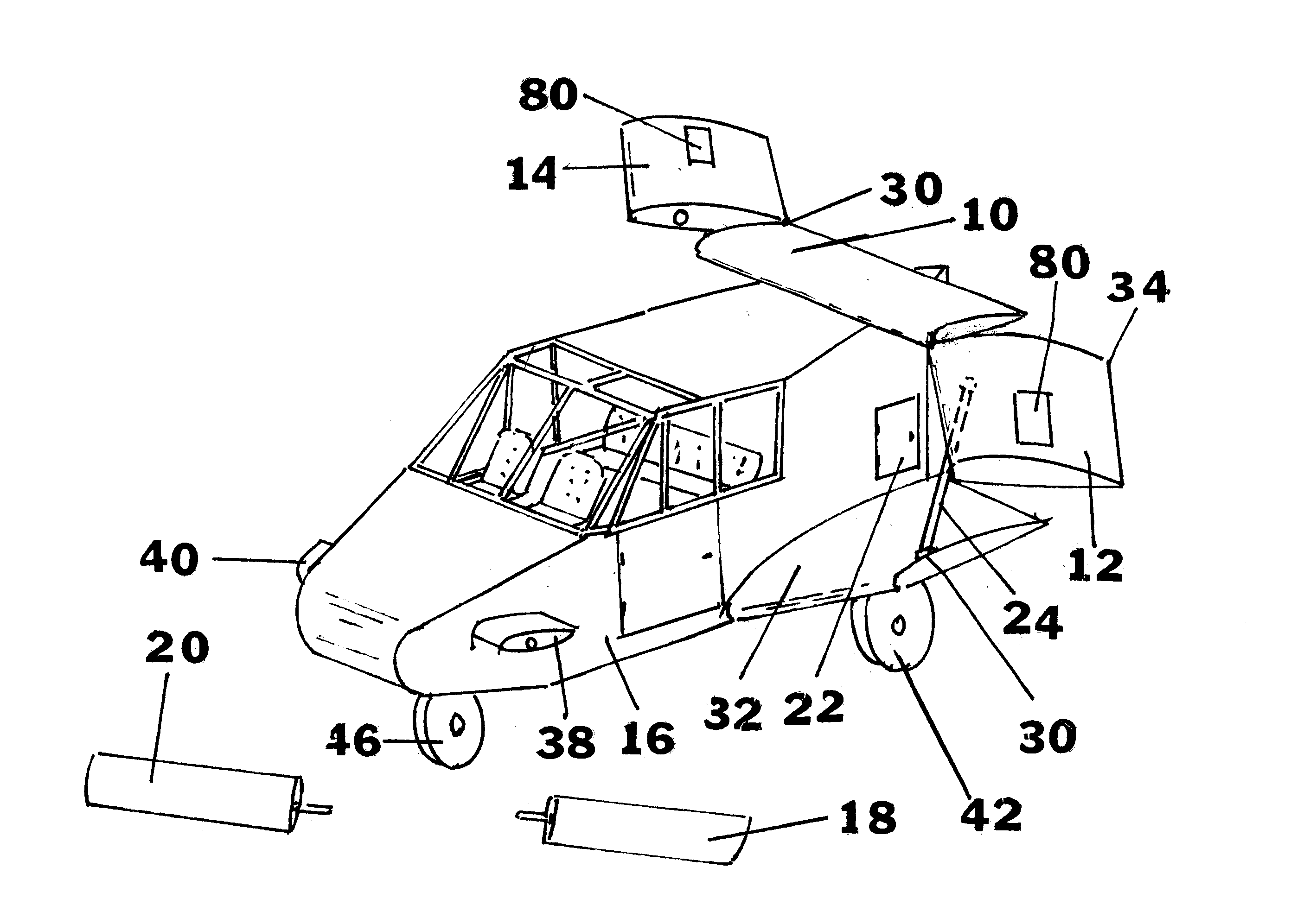
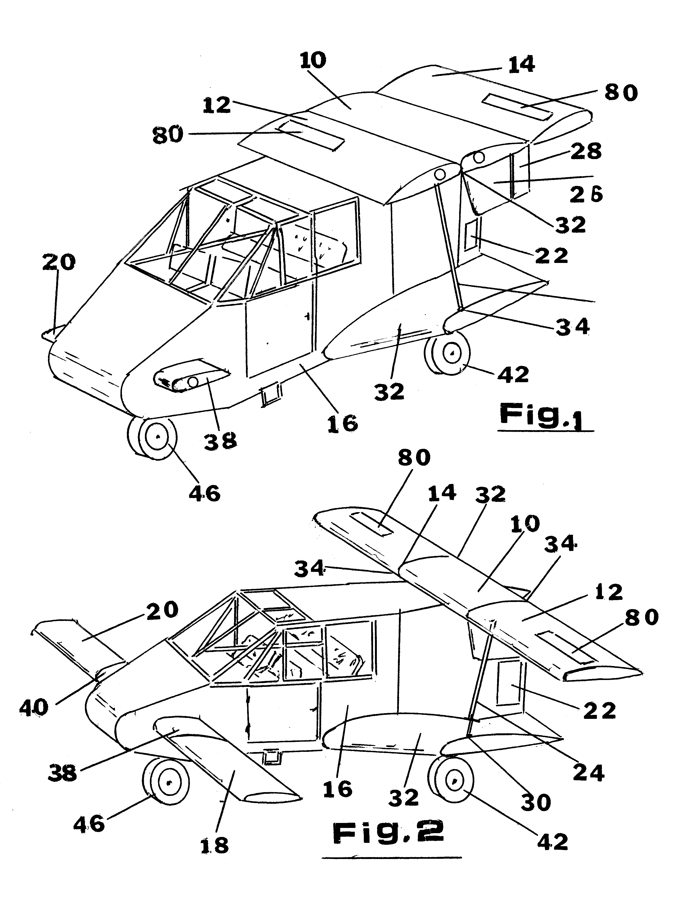
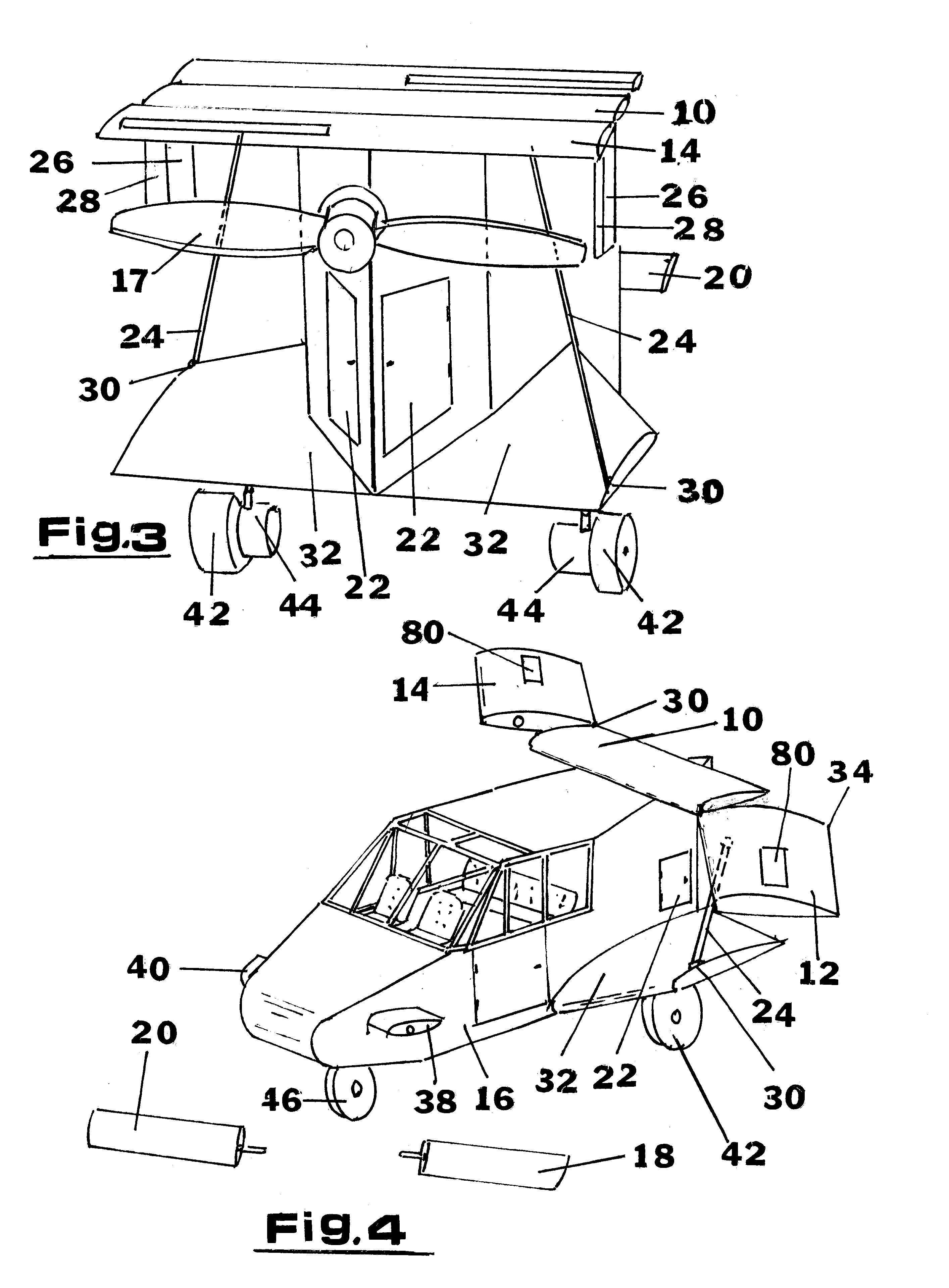
Referring to FIG. 1, a roadable aircraft embodying the invention is shown generally converted for road use with a center main wing section 10, outer main wing sections 12 and 14 stored on the upper surface of a fuselage 16. Outer canard sections 18 and 20, not shown, are stored within the fuselage 16, entry being made through access panels 22. Wing struts 24 are used to assist in the main wing rotation and also in support during road use and in flight. A vertical stabilizer 26 with a rudder 28 is shown affixed to the underside main center wing 10. A second (twin) vertical stabilizer and rudder is not shown. Drag panels 80 shown would not be used if the vertical stabilizer 26 and the rudder 28 are used. Of importance is the location of the strut 24 pivot point 30 on a fuselage lifting surface 32 which strut 35 supports and guides the main wing outer sections 12 and 14 for stowing.

Referring to FIG. 2, a roadable aircraft is shown ready for flight. The main wing outer sections 12 and ...


PUM


Abstract

A pusher canard aircraft convertible for road use. Canard outer sections are removable and are stored within the aircraft fuselage and the outer main wing sections rotate horizontally for storage on the fuselage top. The fuselage is designed as a lifting body which gives the aircraft three lifting surfaces. The lifting body takes advantage of ground effect, resulting in a lower landing speed. In road mode the vehicle as a 2 or 4 passenger model is smaller than a full size automobile. Hydraulic motor wheels propel the aircraft / vehicle for road use. An internal combustion engine within the fuselage drives the propeller for air operation. The propeller is disengaged, not removed, for land operation and the engine is used to drive an hydraulic pump to power the motor wheels for road use. A single nose wheel or two front wheels are used for both steering in landing / taxiing and for road use. In road mode, the appearance is as much like a van than as an aircraft. In flying mode, the appearance is not to unconventional.

Description

1. Field of the Invention2. Description of the Relevant ArtSince the Wright Brothers early flights, there has existed a strong desire and a belief that we would soon be driving vehicles that could also fly. That desire and belief exists today and attempts are still being made to arrive at a satisfactory and practical solution. There have been some successful flights of "flying cars" and even some that achieved certification, but none have proven practical.The failures in achieving practical success were due, in part, to the designs which were attempts to add the flying components to existing or special cars. These designs required the flying components to be stored at an airport or trailered behind its car. The additional heavy weight of the flying car required large wing surfaces and high power. These components, wing, tail and propeller are relatively light and leaving them exposed, at an airport, to the wind and other outdoor elements leaves much to be desired. Flying to an airpo...

Claims


Application Information

Patent Timeline
Patent Type & Authority Patents(United States)
IPC IPC(8): B64C39/12B64C37/00B64C5/00B64C39/00B64C5/12B64C3/00B64C3/56
CPCB64C3/56B64C5/12B64C37/00B64C39/12Y02T50/145Y02T50/10
Inventor EINSTEIN, HARRY
Owner EINSTEIN HARRY
Why Eureka
Try Eureka