Optical recording medium

a recording medium and optical technology, applied in the field of optical recording mediums, can solve the problems of easy errors, deterioration of information on a certain track, and deterioration of the recording mark of the track,

Inactive Publication Date: 2004-10-19
KK TOSHIBA
View PDF7 Cites 14 Cited by
  • Summary
  • Abstract
  • Description
  • Claims
  • Application Information

AI Technical Summary

Problems solved by technology

However, if the recording marks are close to each other, the amplitude of the signal is small, so that errors are easy to occur when the signal is converted into digital data.
However, in this method, there is a problem in that, in a region in which a track pitch is substantially equal to or smaller than the size of a light beam, there is caused a so-called cross erase wherein information on a certain track deteriorates when a writing or erasing operation is carried out in an adjacent track.
One cause is that, when adjacent tracks are irradiated with a beam, the light intensity of the beam at the bottom edge thereof within a subject track is not small, so that the recording mark of the track is deteriorated by only the effect of irradiation with light.
The other cause is that, when adjacent tracks are heated by a light beam, generated heat is transferred to the tracks by heat transfer in film in-plane directions, so that the shape of a recording mark is deteriorated by the influence thereof.
However, if the dielectric film 303 is too thin, heat transfer to the reflecting film 302 starts simultaneously with heating due to laser beams during recording, so that there is a problem in that the temperature rise of the recording film 304 is insufficient, whereby the temperature of an area required to form a recording mark does not reach the melting point.
Therefore, the temperature of the mark can not be held in a temperature range capable of crystallizing the mark for a sufficiently long time, so that there is a problem in that it is difficult to crystallize the mark, i.e. to carry out an erasing operation, thereby remarkably deteriorating the erasing rate.
However, as described above, heat transfer into the plane of the film is not only promoted to violently cause cross erase, but the cooling rate of the recording film 304 is slow.
Therefore, there is a problem in that the region melt during recording is crystallized again without being amorphous, so that the formed mark is too small.
However, since this method does not sufficiently select the material of the intermediate layer and selects a material having a low thermal conductivity, it is difficult to carry out rapid cooling, so that this method can not sufficiently reduce cross erase.
However, conventional means can not simultaneously satisfy all of them.

Method used


Image

  • Optical recording medium
  • Optical recording medium
  • Optical recording medium

Examples


first embodiment

(First Embodiment)

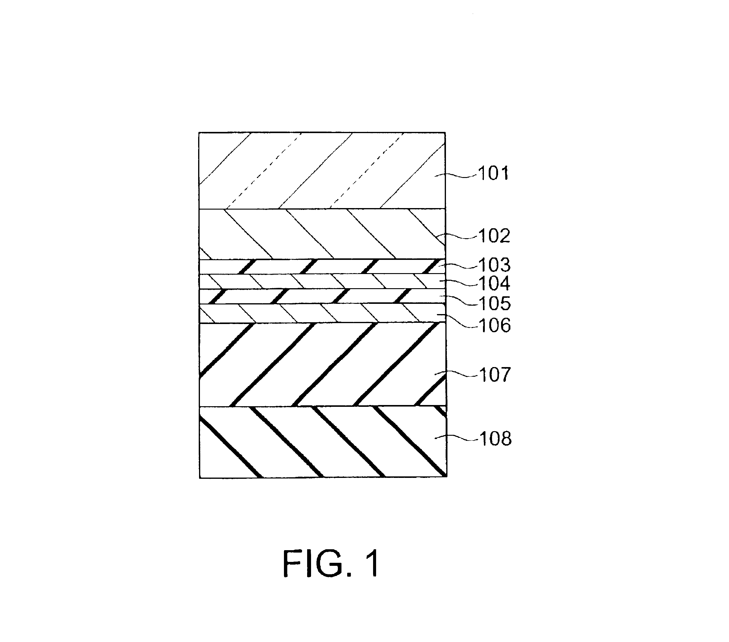
The construction of the first embodiment of a phase change optical recording medium according to the present invention is shown in FIG. 1. This phase change optical recording medium in the first embodiment satisfies the above described requests (1) to (3), and comprises a substrate 101 of, e.g., polycarbonate, a metal reflecting film 102 formed on the substrate 101, a transparent dielectric film 103 formed on the metal reflecting film 102, a semitransparent metal film 104 formed on the dielectric film 103, a transparent dielectric film 105 formed on the semitransparent metal film 104, a recording film formed on the dielectric film 105, a transparent dielectric film 107 formed on the recording film 106, and a cover layer 108 formed on the dielectric film 107.

This phase change optical recording medium in the first embodiment can reduce cross erase. Referring to the drawings, this will be described in detail. With respect to characteristics of the recording film 106 f...

second embodiment

(Second Embodiment)

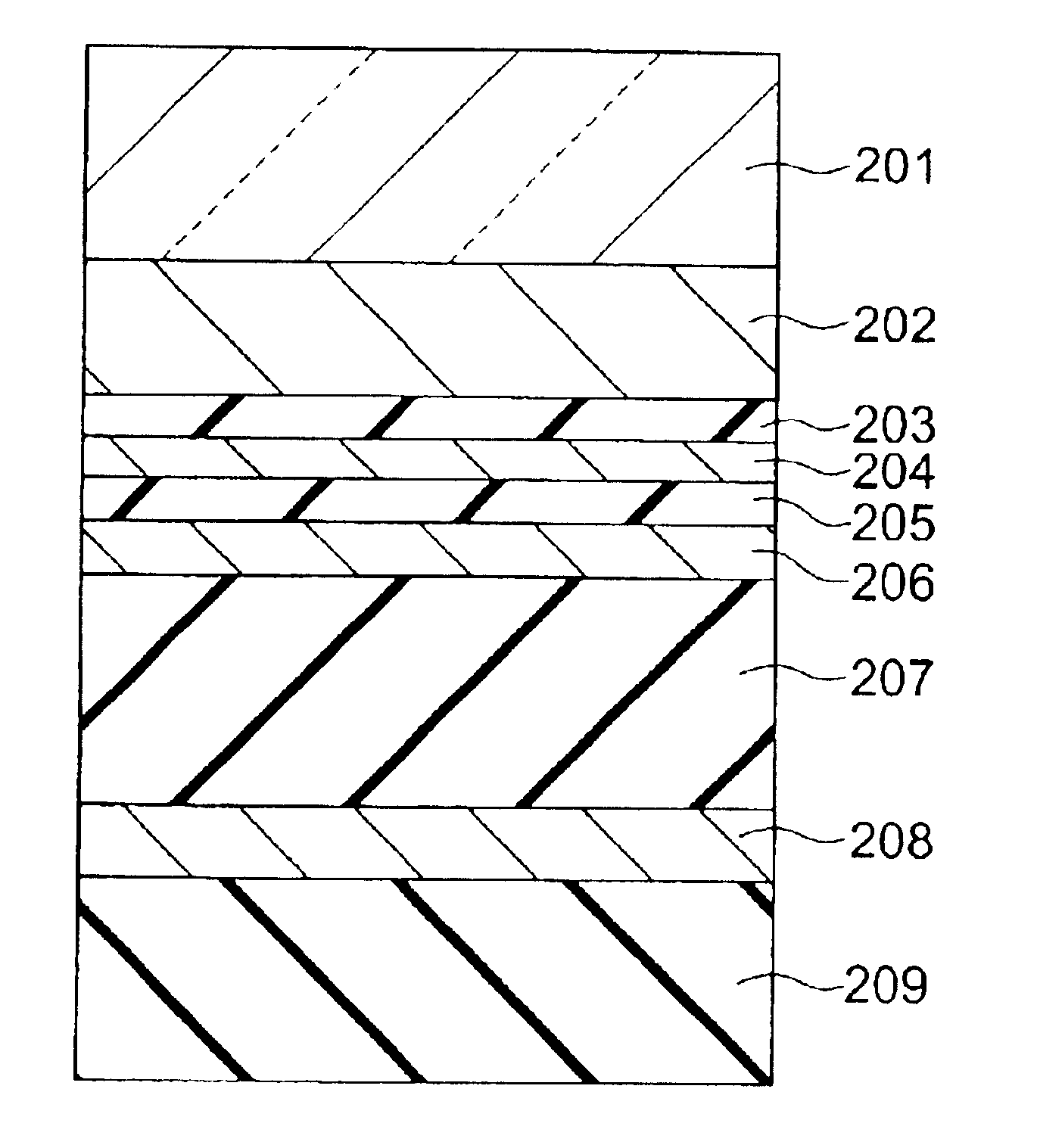
Referring to FIG. 9, the second embodiment of a phase change optical recording medium according to the present invention will be described below. The phase change optical recording medium in this embodiment has a construction wherein a metal reflecting film 202, a transparent dielectric film 203, a semitransparent metal film 204, a dielectric film 205, a recording film 206, a dielectric film 207, a semitransparent metal film 208 and a cover layer 209 are sequentially stacked on a substrate 201 of polycarbonate. That is, in the phase change optical recording medium in the first embodiment, another semitransparent metal film 208 is provided on the light incident side.

The features of this embodiment are as follows. In the conventional construction shown in FIG. 10, i.e. in the construction wherein three layers of dielectric / semitransparent film / dielectric film are provided between a recording film 304 and a metal reflecting film 302, it is not possible to enhance the...


PUM

PropertyMeasurementUnit
distanceaaaaaaaaaa
distanceaaaaaaaaaa
thicknessaaaaaaaaaa

Abstract

There is provided an optical recording medium capable of preventing cross erase and increasing its recording density. The optical recording medium includes: a reflecting film; a first transparent film provided on the reflecting film; a first semitransparent film provided on the first transparent film; a second transparent film provided on the first semitransparent film; a recording film provided on the second transparent film, the recording film being capable of reversibly changing an atomic arrangement; and a third transparent film provided on the recording film. The first semitransparent film has a complex refractive index of n-k satisfying relationships of 0<n<1 and 1<k, and a product of a thickness d (nm) of the first semitransparent film and an extinction coefficient k of the complex refractive index is dxk<=44.

Description

This application is based upon and claims the benefit of priority from the prior Japanese Patent Application No. 2002-86297 filed on Mar. 26, 2002 in Japan, the entire contents of which are incorporated by reference.1. Field of the InventionThe present invention generally relates to an optical recording medium for reversibly changing a state by irradiation with light beams to record information. More specifically,the invention relates to a phase change optical recording medium which has a change of state wherein the atomic arrangement of a thin film for holding recording changes between amorphous and crystalline arrangements.2. Related ArtA typical phase change optical recording film has an amorphous atomic arrangement when its portion heated to its melting point or higher to melt is rapidly cooled. When the phase change optical recording film is held in a crystallized temperature range below the melting point for a predetermined time or longer, it is crystallized if its initial sta...

Claims


Application Information

Patent Timeline
Patent Type & Authority Patents(United States)
IPC IPC(8): G11B7/243G11B7/24G11B7/257G11B7/241G11B7/24027G11B7/2433
CPCG11B7/00557G11B7/2403G11B7/243G11B7/257G11B7/00454G11B7/0062Y10T428/21G11B2007/25706G11B2007/25708G11B2007/2571G11B2007/25713G11B7/24027G11B7/2433
Inventor ASHIDA, SUMIOYUSU, KEIICHIROICHIHARA, KATSUTARONAKAMURA, NAOMASAOHMACHI, NORITAKE
Owner KK TOSHIBA
Why Eureka
Try Eureka