
Coated optical fiber

a technology of optical fiber and coating, applied in the field of coating optical fiber, can solve the problems of unsatisfactory coating such as primary coating or secondary or other coatings on the surface of glass optical fiber, and achieve the effects of shortening the curing time, reducing the delamination on the production line, and enhancing the collective stripping of coatings

Inactive Publication Date: 2004-10-26
SUMITOMO ELECTRIC IND LTD
View PDF6 Cites 59 Cited by
  • Summary
  • Abstract
  • Description
  • Claims
  • Application Information

AI Technical Summary

Benefits of technology

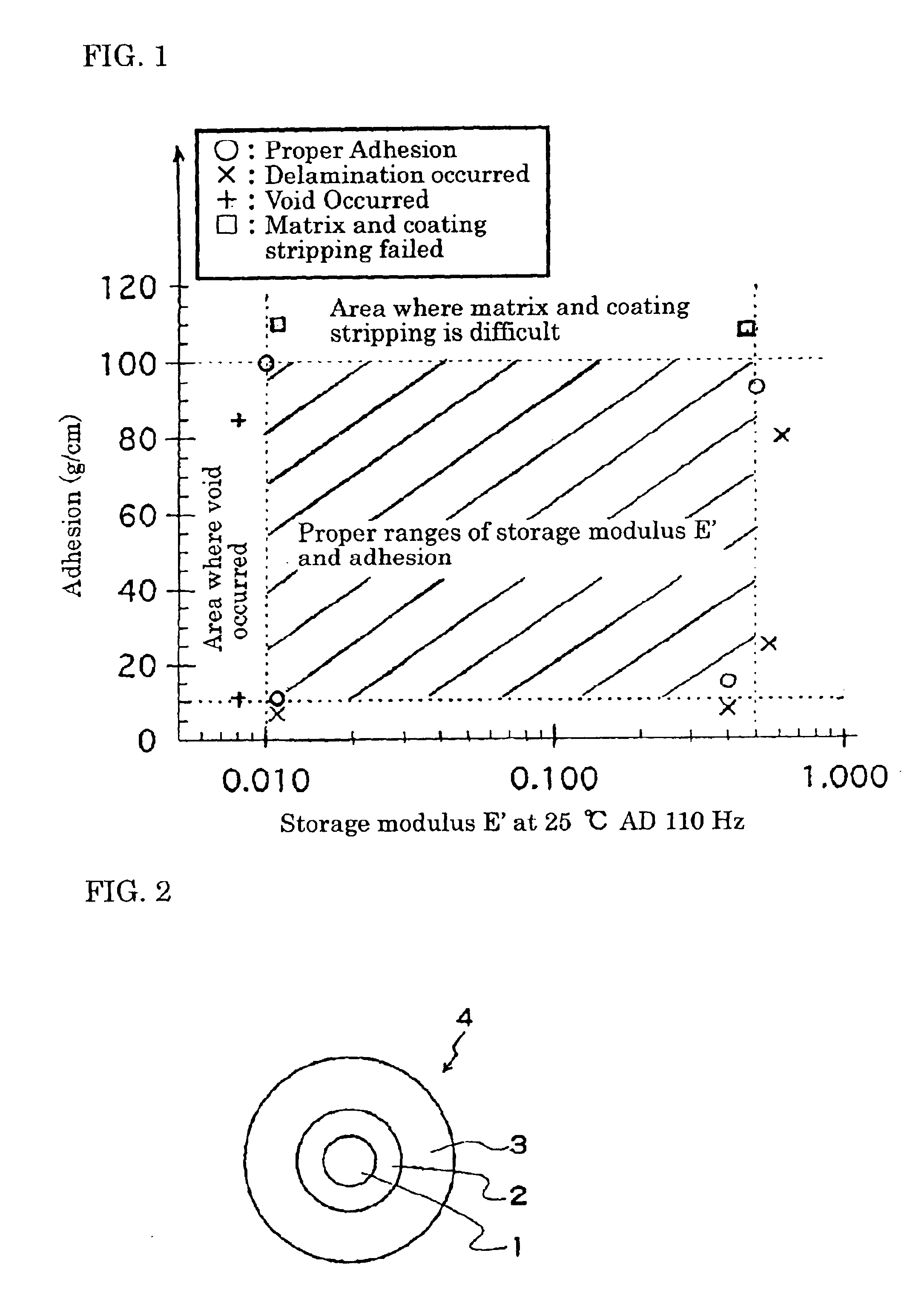
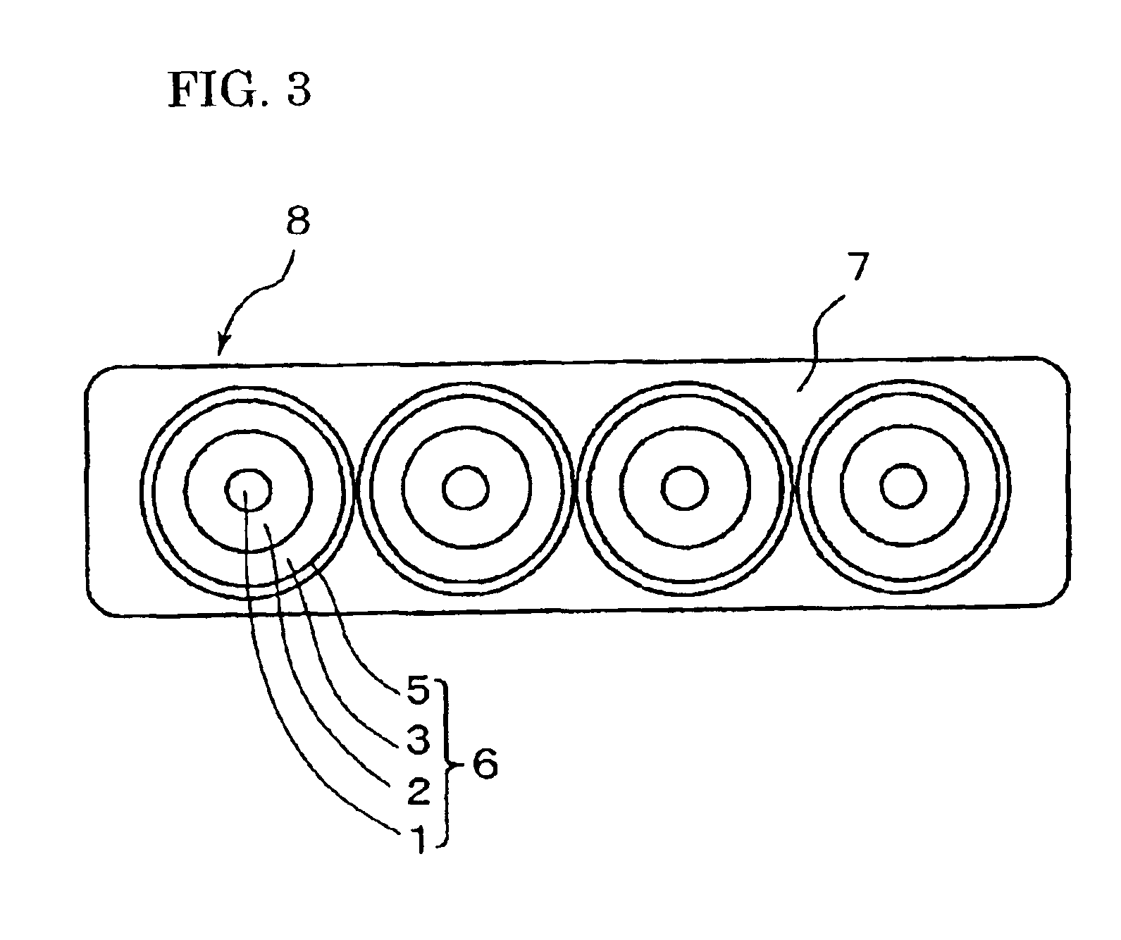
The present invention relates to a coated optical fiber and an optical fiber ribbon. The coated optical fiber has a primary coating with a storage modulus of 0.01 kg / mm.sup.2 to 2.0 kg / mm.sup.2 at +25°C and a glass optical fiber with an adhesion between them of 10 g / cm to 200 g / cm. The primary coating is made of ultraviolet curable resin. The optical fiber ribbon has multiple coated optical fibers arranged in parallel and collectively coated with a unitary resin jacket. The invention aims to achieve better delamination resistance and adhesion between the coating and the glass optical fiber.

Problems solved by technology

In this case, it is undesirable that the coatings such as the primary coating or secondary or other coatings remain on the surface of the glass optical fiber.

Method used


Image

  • Coated optical fiber
  • Coated optical fiber
  • Coated optical fiber

Examples


examples 1 to 4

, Comparative Examples 1 to 4, and Comparative Examples 1' to 4

When producing a two-layers coated optical fiber in which a primary coating was formed around the outside of a quartz glass optical fiber having an outer diameter of 125 .mu.m so as to obtain an outer diameter of 200 .mu.m, and a secondary coating was formed therearound so as to obtain an outer diameter of 240 .mu.m, a relatively soft photo-curable urethane acrylate resin was used as the material of the primary coating, and a relatively hard photo-curable urethane acrylate resin was used as the secondary coating.

In order to adjust the adhesion, resins were prepared as the material of the primary coating, in which a polar monomer (for example, acrylamide, N-vinylpyrrolidone, or acryloyl morpholine) or a silane-coupling agent was contained at different rates.

First, tests were conducted to measure the storage modulus E' of the primary coating materials and the adhesion thereof to glass which was the same material as that of...


PUM

PropertyMeasurementUnit
frequencyaaaaaaaaaa
temperatureaaaaaaaaaa

Abstract

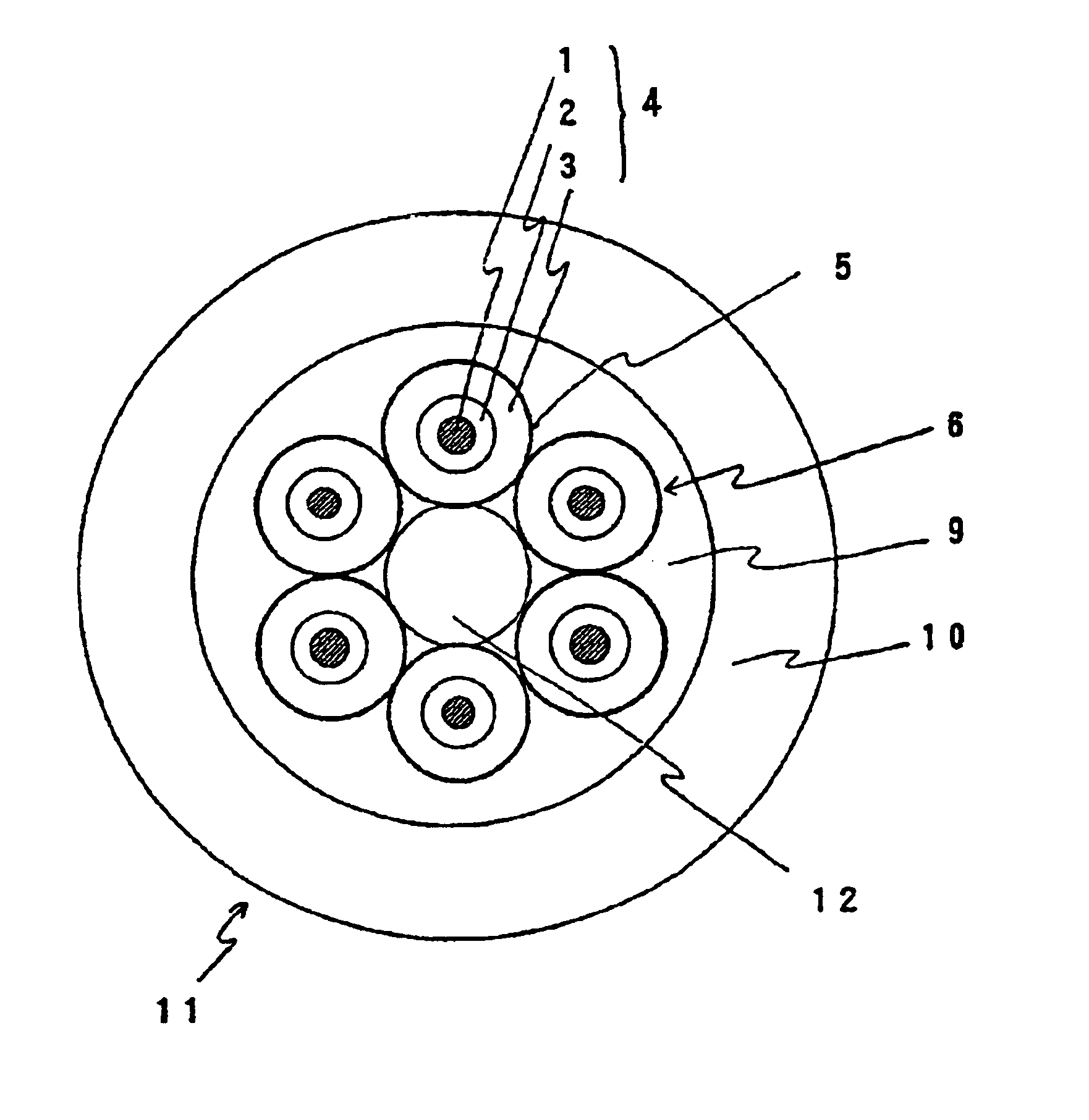
A coated optical fiber is shown in which, by coating a glass optical fiber with a primary coating having a storage modulus E' of 0.01 kg / mm<2 >to 2.0 kg / mm<2 >at 25° and 110 Hz and an adhesion of 10 g / cm to 200 g / cm to the glass optical fiber, delamination at the interface between the glass optical fiber and the primary coating, and voids are prevented during and after the production, for example, on the line during drawing and winding. An optical fiber ribbon of the present invention, which is formed by collectively coating the coated optical fibers each including a primary coating with a storage modulus E' of 0.01 kg / mm<2 >to 0.5 kg / mm<2 >and an adhesion of 10 g / cm to 100 g / m, has a high delamination resistance and a good collective strippability of coatings. In an optical fiber unit of the present invention which is formed by collectively coating the coated optical fibers having a storage modulus E' of 0.01 kg / mm<2 >to 0.5 kg / mm<2 >and an adhesion of 100 g / cm to 200 g / cm, delamination and voids will not occur.

Description

The present invention relates to a coated optical fiber, an optical fiber ribbon, and an optical fiber unit.An optical fiber is obtained by drawing an optical fiber preform having at least a core and a cladding. Immediately after drawing, a coating is formed around the outside of the glass optical fiber in order to protect and reinforce the fiber and to give it flexibility, and for other purposes. It is known to form at least two layered coatings, namely, a relatively soft (low Young's modulus) primary coating which is in contact with the outer circumference of the glass optical fiber and which has a buffering function, and a hard (high Young's modulus) secondary coating formed on the outermost side and having a protective function.For example, a coated optical fiber is proposed in Japanese Patent Application Laid open No. 9-5587, in which, by setting the extraction force (the force necessary to pull a glass optical fiber out of the coated optical fiber which is fixed from the outsi...

Claims


Application Information

Patent Timeline
Patent Type & Authority Patents(United States)
IPC IPC(8): C03C25/10G02B6/02G02B6/44
CPCG02B6/02395G02B6/443G02B6/44
Inventor SUZUKI, ATSUSHIHATTORI, TOMOYUKITANAKA, KAZUNORIHOSOYA, TOSHIFUMI
Owner SUMITOMO ELECTRIC IND LTD
Learn More