Zirconium alloy having excellent corrosion resistance and mechanical properties for nuclear fuel cladding tube
a technology of zirconium alloys and nuclear fuel, which is applied in the direction of distance measurement, greenhouse gas reduction, instruments, etc., can solve the problems of poor corrosion resistance, affecting workability, and causing problems such as workability
- Summary
- Abstract
- Description
- Claims
- Application Information
AI Technical Summary
Benefits of technology
Problems solved by technology
Method used
Image
Examples
example 1
Preparation of Zirconium Alloy Nuclear Fuel Cladding Tube
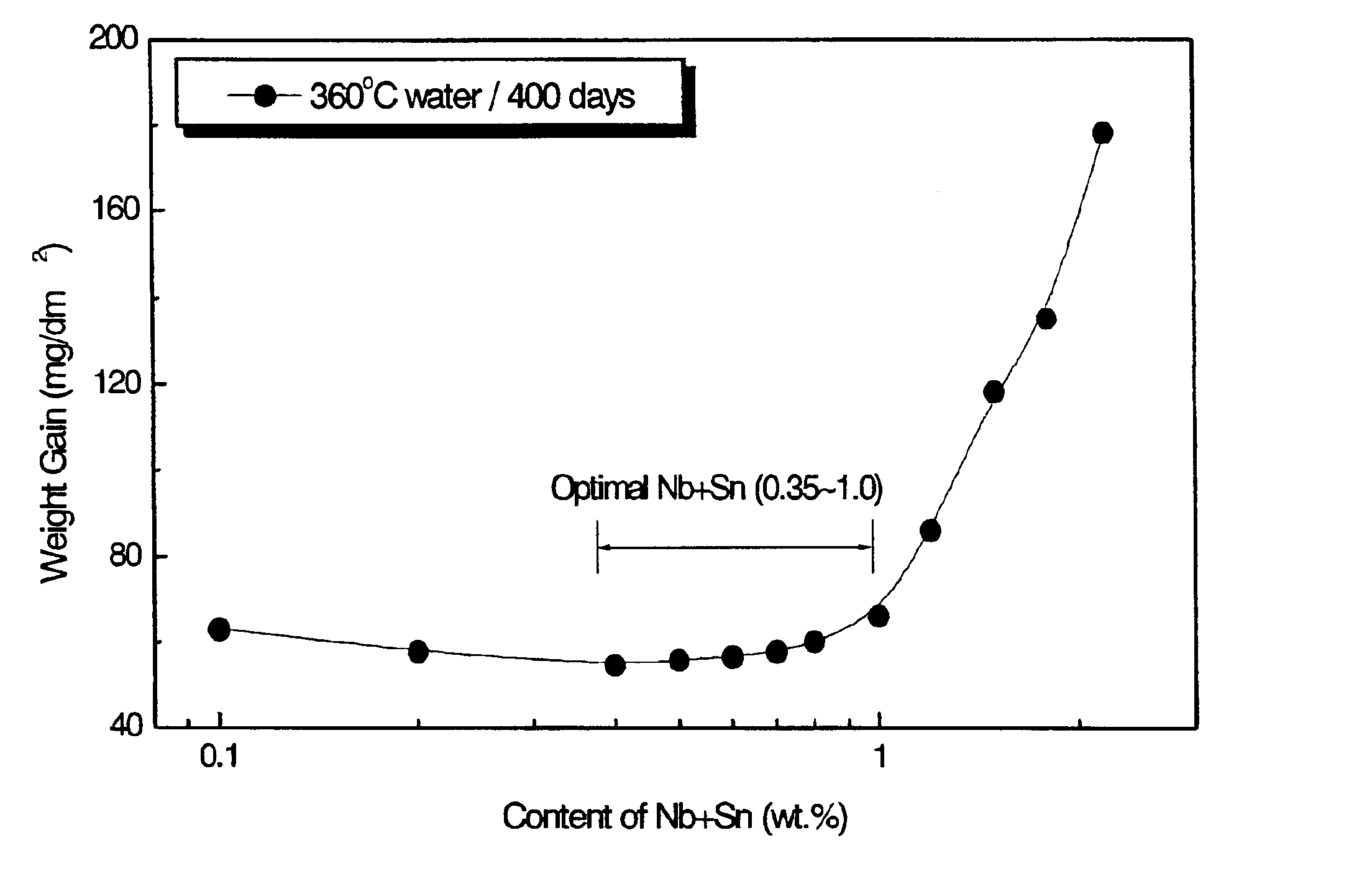
To confirm an effect of very small amounts of elements to be added to a zirconium alloy, a mixture comprising Zr-aNb-bSn-cFe-dCr-eCu (a=0.05-0.4 wt %, b=0.3-0.7 wt %, c=0.1-0.4 wt %, d=0-0.2 wt %, e=0.01-0.2 wt %, provided that, a+b=0.35-1.0 wt %), as shown in the above table 1, was melted in a vacuum arc melting furnace to obtain the ingot of the alloy. Forging was carried out at .beta. phase range of 1200.degree. C. to break its dentrite structure in the ingot. Subsequently, through .beta.-quenching process in which solution heat treatment was performed at 1050.degree. C. to uniformly distribute alloy elements and then a rapid cooling was performed, thereby yielding a martensitic or a widmanstattenic structure. The .beta.-quenched ingot was worked to hot working at 630.degree. C. to make an extruded shell suitable for cold working. The extruded shell prepated in the fourth step is cold-working to obtain a TREX. Subsequently,...
experimental example 1
Observation of Microstructure According to Each Preparation Step
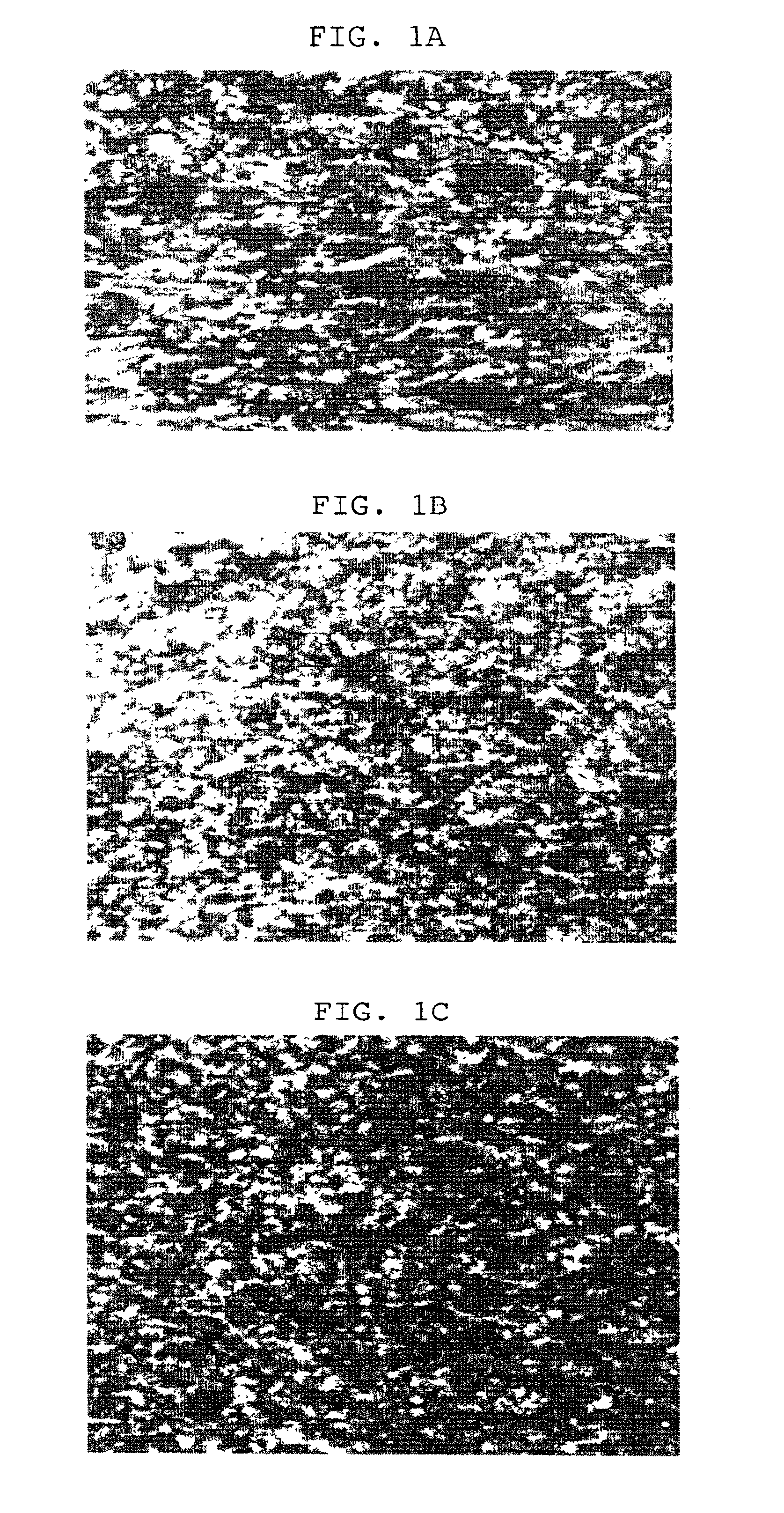
Referring to FIGS. 1a to 1c, there are shown photomicrographs of microstructures according to each preparation step of an experimental alloy 1 (standard alloy). A test piece for observing microstructures was abraded by #2000 SiC abrasive paper, and etched with HF (10 wt %)+HNO.sub.3 (45 wt %)+H.sub.2 O (45 wt %)
In observing microstructures by use of a polarization microscope, the wholly recrystallized structure being distorted in some parts according to a working direction was seen when the first intermediate vacuum annealing was performed at 590.degree. C. for 3 hours. Then, recrystallization was totally completed by a second and a third intermediate vacuum annealing carried out at 570.degree. C. for 2 hours. As for the elongation of crystallization granules according to working treatment, it is performed in the microstructure after the first intermediate vacuum annealing and, to lesser extent, after the second and the...
experimental example 2
Observation of Final Microstructure
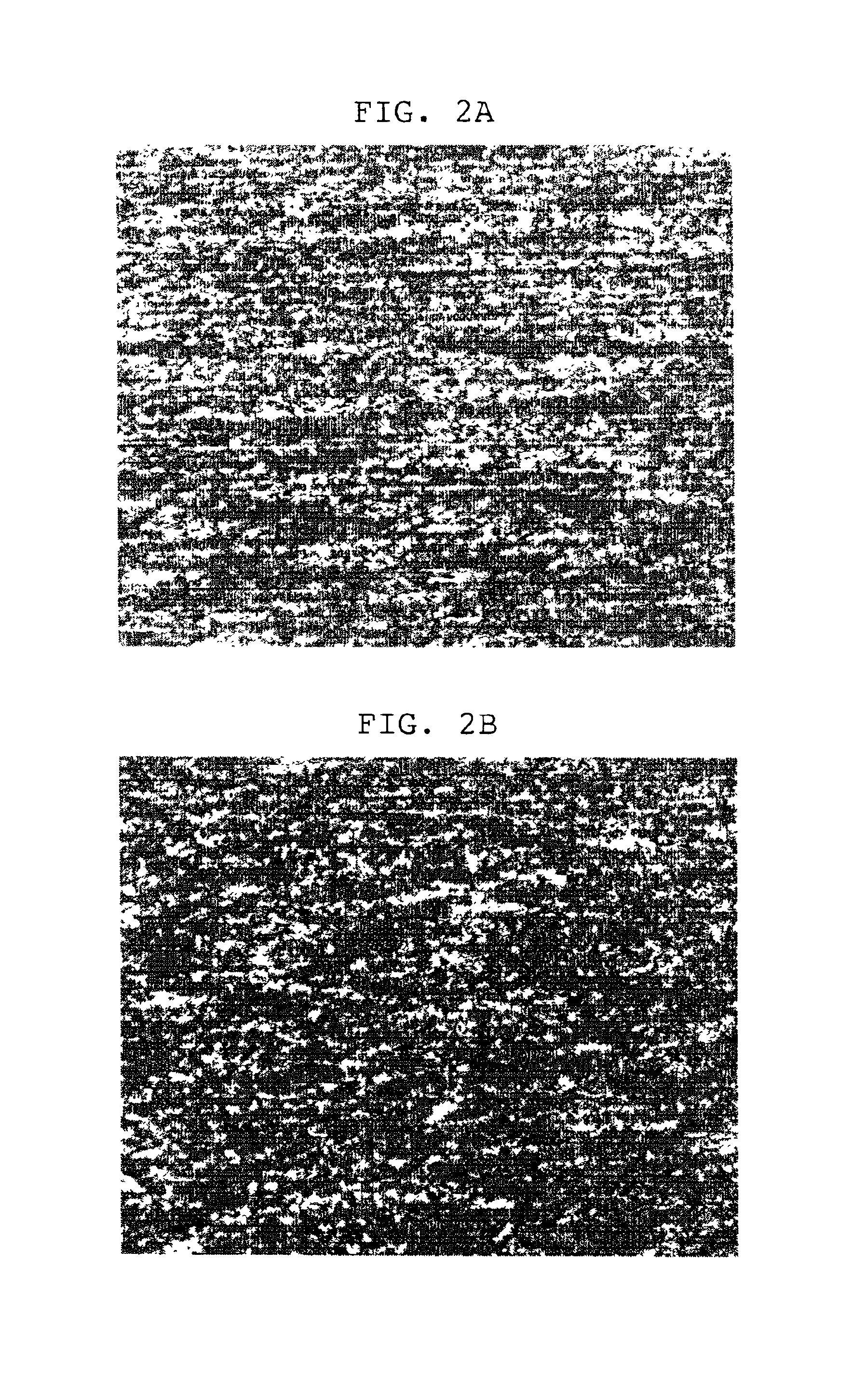
After the experimental alloy 1 (standard alloy) was subjected to last cold-working, final vacuum annealing was conducted at a temperature range of from 470.degree. C. for stress relief annealing to 520.degree. C. for partial recrystallization, for 2.5 hours to prepare the test pieces in the same manner as in the above experimental example 1, which were then observed for their microstructures.
FIGS. 2a and 2b show microstructures of the pieces after stress relief annealing and partial recrystallization, which illustrate all intended structure types. When final vacuum annealing was performed at this temperature range (470-520.degree. C.), very preferable corrosion resistance and mechanical properties were obtained.
PUM
| Property | Measurement | Unit |
|---|---|---|
| temperature | aaaaa | aaaaa |
| temperature | aaaaa | aaaaa |
| temperature | aaaaa | aaaaa |
Abstract
Description
Claims
Application Information
 - R&D
- Intellectual Property
- Life Sciences
- Materials
- Tech Scout
- Unparalleled Data Quality
- Higher Quality Content
- 60% Fewer Hallucinations
Browse by: Latest US Patents, China's latest patents, Technical Efficacy Thesaurus, Application Domain, Technology Topic, Popular Technical Reports.
© 2025 PatSnap. All rights reserved.Legal|Privacy policy|Modern Slavery Act Transparency Statement|Sitemap|About US| Contact US: help@patsnap.com


