Combination tool with automated tool change for robot assisted assembly

a technology of robot assisted assembly and tooling, which is applied in the direction of manufacturing tools, precision positioning equipment, transportation and packaging, etc., can solve the problems of inability to adapt to inability to meet the needs of different types of robots, etc., to achieve easy adjustment, reduce cycle time, and save time and cost

Inactive Publication Date: 2005-01-04
SYMBOTIC CANADA ULC
View PDF2 Cites 4 Cited by
  • Summary
  • Abstract
  • Description
  • Claims
  • Application Information

AI Technical Summary

Benefits of technology

A significant advantage of the invention is that cycle time is reduced by simultaneous manufacturing operations carried out by at least two arms on a combination tool resulting in time and cost savings. The combined tool includes means to grip the part, laser scan the workpiece, calculate any offsets required for proper positioning within predetermined tolerances, heating plastic part surfaces and workpiece part surfaces simultaneously, and pressing heated surfaces together to form a thermal plastic weld joint and impervious fluid seal.
It will be understood that plastic welding is used only as an example to describe one application of the invention and that the tool is readily adaptable and equally advantageously used for robot assisted assembly in any number of alternative technologies. For example, the tool can be used for heating plastic surfaces, adhesive application, sealant application, grinding or abrading, or cutting surfaces by replacing the surface preparation modules mounted on the multiple arms of the combination tool. Packaging multiples tools together in a flexible combination tool that can be easily modified for various applications, provides a much higher degree of flexibility and quick tool change over compared with conventional assembly operations.
In the prior art, welding plastic parts in the automotive industry for example, involves applying heat to the workpiece and / or heat to the part, then exerting sufficient pressure to bond the plastic surfaces together providing a seal and physical joint. Conventional operations utilize two separate tools and two separate robots. One robot with one tool is used for preparation or heating of the workpiece. A second robot and tool is used for preparation or heating of the part, and assembling the part to the workpiece. The capital costs, maintenance and programming involved in operating two separate robots for two separate operations is expensive and undesirable. However manufacturers are under pressure to deliver relatively low volumes of assemblies in decreasing amounts of time due to changes in manufacturing practices, such as “just in time” delivery and extremely low inventory levels. Rapid adaptation and customization of orders is becoming more and more desirable, so the high degree of flexibility obtained through separating robot operations has been considered necessary.
An alternative assembly method is a conventional automated assembly line with separated dedicated fixtures, jigs and tools that prepare the workpiece and part separately and assemble them in a staggered or step wise conveyed fashion. Such dedicated tools are generally less flexible, less expensive and require less technical sophistication than robots. However, these benefits come at the expense of increased cycle time and increased costs in long term operation due to the extensive downtime and cost of changeovers and tool refitting when a new product style is manufactured.
Increasingly, auto parts manufacturers in particular are required to deliver parts to an assembler “just in time” which results in much shorter runs of a particular part design. Rapid tool changeover and rapid adaptation for various styles of assemblies or different assemblies altogether is becoming essential in a highly competitive auto parts manufacturing environment. As a result, the separate dedicated tools that are suitable for long high volume runs at low cost are becoming less and less economically viable whereas processes that provide high degrees and flexibility and rapid changeover for different styles are becoming the norm.
As an example, with separate dedicated tools an automobile part supplier would set up a separate manufacturing line for gas tanks, bumpers, fenders, dashboards and other commoncomponents. The economic viability of such specialized lines depends on high volume orders and long production runs, preferably with very little change in the design of individual products or the general layout of the manufacturing facility. Increasingly however manufacturers require delivery of parts from suppliers in smaller volumes and with less lead time than in the past. In addition, pressures to lower costs and speed up tool changeovers are forcing manufacturers to consider much more flexible manufacturing procedures involving robots, component handling and conveyor systems that can be programmed or adapted for multiple functions.

Problems solved by technology

The capital costs, maintenance and programming involved in operating two separate robots for two separate operations is expensive and undesirable.
However manufacturers are under pressure to deliver relatively low volumes of assemblies in decreasing amounts of time due to changes in manufacturing practices, such as “just in time” delivery and extremely low inventory levels.
Such dedicated tools are generally less flexible, less expensive and require less technical sophistication than robots.
However, these benefits come at the expense of increased cycle time and increased costs in long term operation due to the extensive downtime and cost of changeovers and tool refitting when a new product style is manufactured.
Increasingly, auto parts manufacturers in particular are required to deliver parts to an assembler “just in time” which results in much shorter runs of a particular part design.
As a result, the separate dedicated tools that are suitable for long high volume runs at low cost are becoming less and less economically viable whereas processes that provide high degrees and flexibility and rapid changeover for different styles are becoming the norm.

Method used


Image

  • Combination tool with automated tool change for robot assisted assembly
  • Combination tool with automated tool change for robot assisted assembly
  • Combination tool with automated tool change for robot assisted assembly

Examples


Embodiment Construction

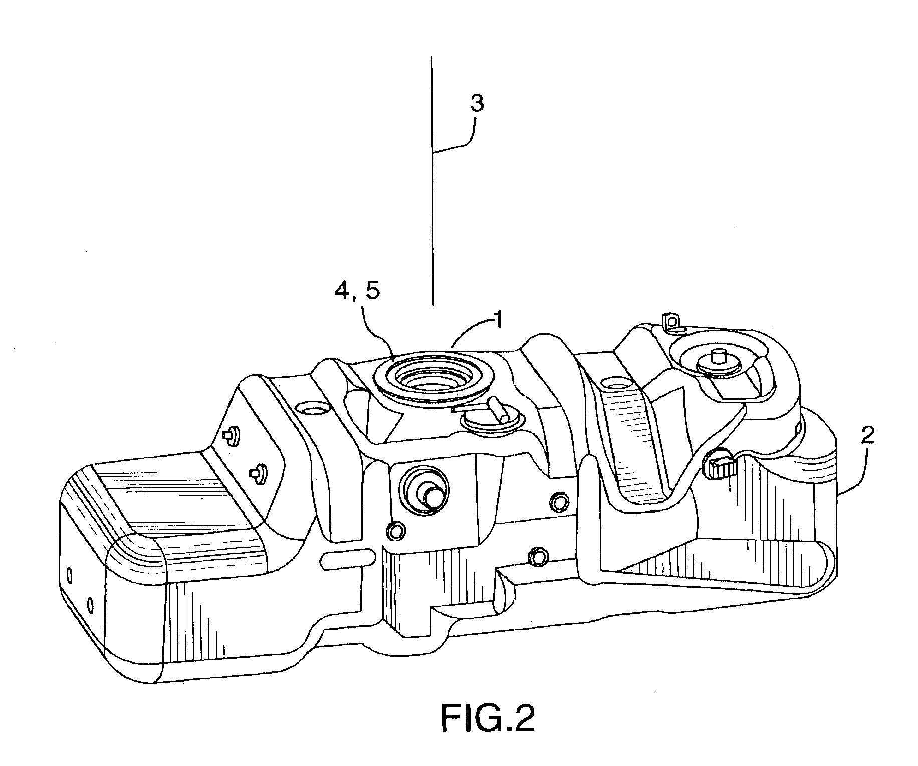
FIG. 2 shows an example workpiece 2 in the form of a blow moulded plastic gas tank which includes a fitting known as a “sender ring”. For simplicity the sender ring will be simply identified as the part 1 which is thermally plastic welded to the gas tank workpiece 2 during the operation described below. As seen in FIG. 2 however, the gas tank workpiece 2 includes a number of vents and fittings which may also be installed using the method described here.

The sender ring part 1 and the target surface 5 on the workpiece have an alignment axis that ideally should coincide exactly with the operating axis 3 of the combination tool. The alignment / operating axis 3 is used to orient and align the part 1 on the workpiece 2 and is used as a reference vector. As it is appreciated by those skilled in the art, a blow moulded plastic gas tank may have significant variation in its outer dimensions due to various causes inherent in the manufacturing process such as shrinkage of the thermal plastic ma...


PUM

PropertyMeasurementUnit
rotationaaaaaaaaaa
poweraaaaaaaaaa
pressureaaaaaaaaaa

Abstract

A method of assembling a part to a workpiece with a combination tool supported on a robot, where a mounting surface of the part is assembled on a target surface of the workpiece including the following steps. (a) Indexing to the assembly position. (b) Picking a part with the part gripper on the part delivery arm from a part supply station. (c) Indexing part delivery and workpiece preparation arms to the preparation position. (d) Simultaneously: engaging the part mounting surface with the part surface preparation module; and engaging the workpiece target surface preparation module with the target surface. (e) Indexing to the assembly position. (f) Using the previously set tool operating axis and calculated tool offsets, engaging the prepared part mounting surface with the prepared workpiece target surface. (g) Releasing the part gripper and withdrawing the tool from the part/workpiece assembly.

Description

TECHNICAL FIELDThe invention relates to a method and tool for assembling a part to a workpiece with the tool supported on The invention relates to a method and tool for assembling a part to a workpiece with the tool supported on a robot, where a prepared mounting surface of the part is assembled on a prepared target surface of the workpiece, in a thermal plastic welding process, for example.BACKGROUND OF THE ARTThe invention generally relates to the use of specialized tools or manufacturing processes in the robotic assembly of manufactured components such as automobile parts. In the example used herein, thermal plastic welding of plastic gas tanks for automotive applications is described.The invention provides an assembly tool that is mounted to a conventional robot and a method of robot assisted assembly as a component of a sequential manufacturing process. The process typically involves a robot that is stationary on a pedestal that selects parts from a tray or other stationary sup...

Claims


Application Information

Patent Timeline
Patent Type & Authority Patents(United States)
IPC IPC(8): B23Q16/00B23Q16/02B23Q7/04B23P19/00
CPCB23P19/10B23Q7/048B23Q16/025B23P2700/50Y10T29/49Y10T29/5303Y10T29/49899Y10T29/49826Y10T29/4978Y10T29/49776Y10T29/49885
Inventor BATRIN, MARIUS
Owner SYMBOTIC CANADA ULC
Why Eureka
Try Eureka