
Apparatus for placing rebar in continuously reinforced concrete paving

a technology of continuous reinforcement and rebar, which is applied in the direction of paving reinforcements, building repairs, roads, etc., can solve the problems of inability to support sections of the mat, the life cycle and the ride quality of the concrete road can become severely reduced, and the concrete invariably develops

Inactive Publication Date: 2005-01-04
HARDY CONSTR TECH
View PDF57 Cites 64 Cited by
  • Summary
  • Abstract
  • Description
  • Claims
  • Application Information

AI Technical Summary

Benefits of technology

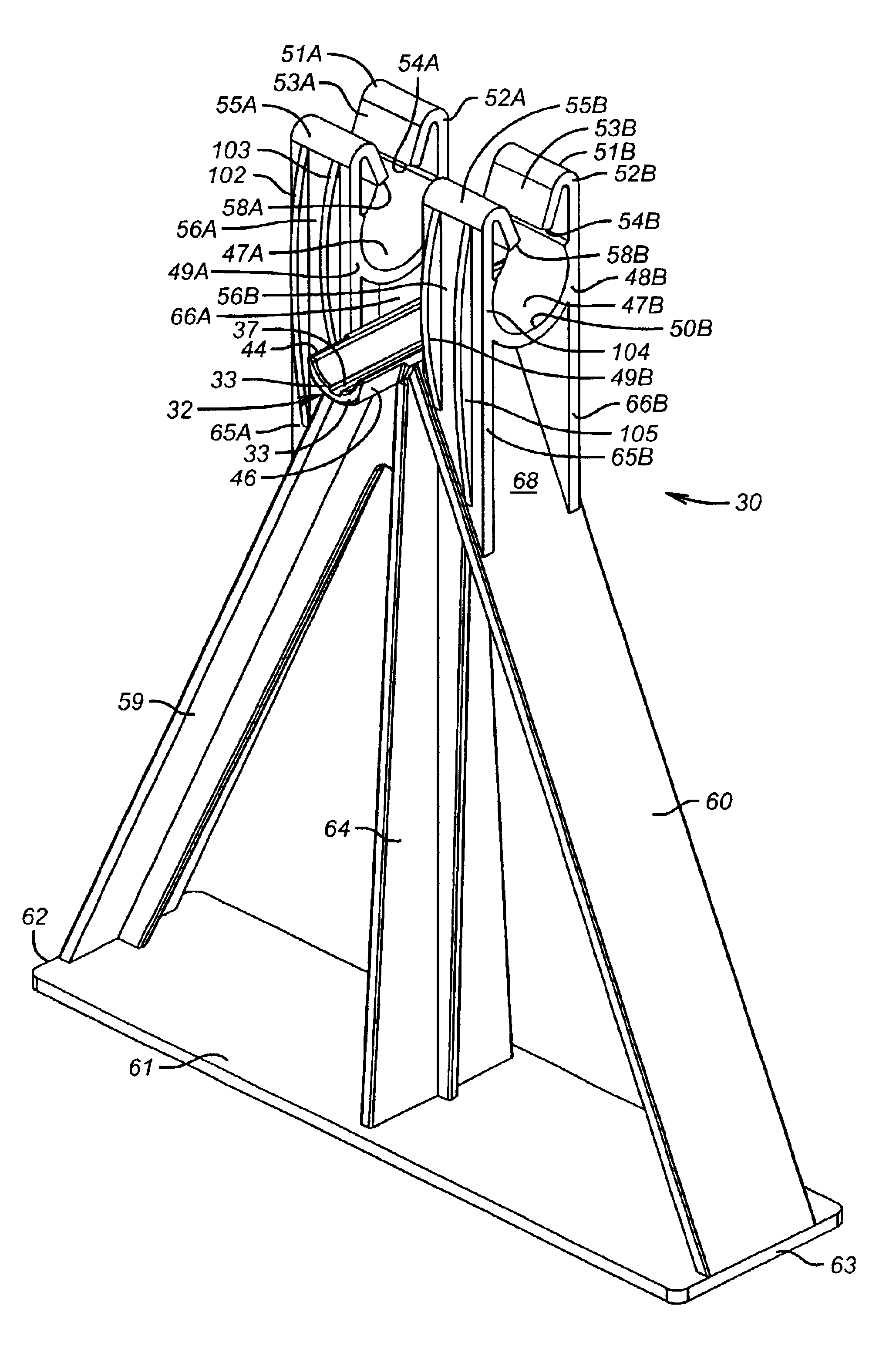
An object of this invention is to provide an alternative rebar chair support to that of U.S. Pat. Nos. 5,893,252 and 6,112,494 that provides similar benefits but avoids the need for a locking cap.
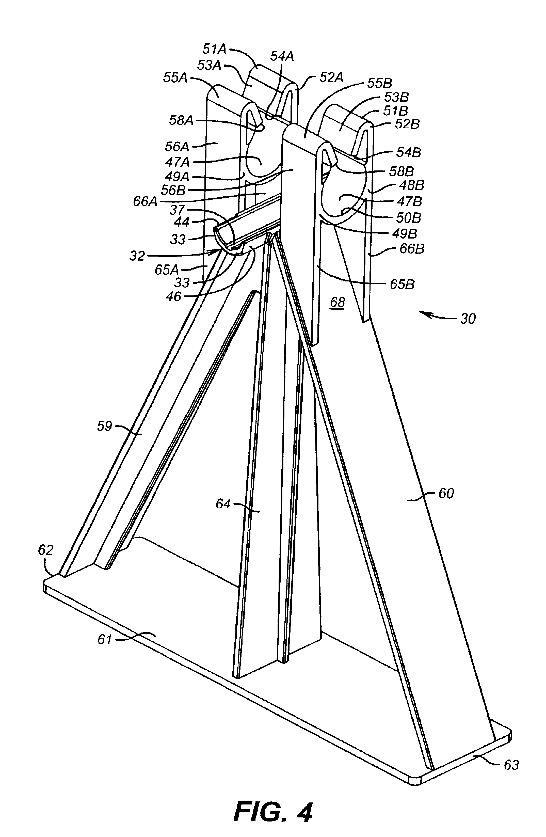
When mounting a saddle or cradle bed piece to a transverse bar after adhesive has been placed on the inside of the saddle or cradle bed, the piece is advantageously tied to the transverse bar by a wrap extending around both the piece and the transverse bar. A plastic tie wrap of the continuously cinching type is quite suitable for this purpose. The tie wrap not only maintains the piece securely in place while the adhesive sets up, but in addition, there being no need to remove it after the bond has formed, the tie further aids in providing resistance to forces that would cause rotational or axial displacement of the pieces before the transverse bar has been made more rotation resistant by insertion of longitudinal bars at the paving site. In order to facilitate the tightness of the tie wrap, the saddle or cradle bed axially extends a distance past the seat for the longitudinal rod and the outer surface of the saddle or cradle bed includes flats shortening the perimeter around the saddle or cradle bed to afford a tighter binding for a tie extending around the outer surface over a transverse bar received in the saddle or cradle bed.

Problems solved by technology

In such applications, however, concrete invariably develops cracks throughout the length of the concrete structure caused by the curing process, load induced stress, weather conditions, and other causes, so that the life cycle and the ride quality of the concrete road can become severely reduced unless some means is used to prevent the concrete from separating along these crack lines.
However, this traditional system of forming and preparing a rebar grid for a concrete pour has several deficiencies.
As the concrete mix is forced under the mat, the chairs are frequently pushed (“rotated”) out from under the mat, causing inadequate support for sections of the mat or in extreme cases, allowing the entire mat to fall.
These metal stakes, however, can produce premature corrosion of the rebar steel by introducing a rust path to the mat steel and by providing a conductor for cathodic corrosion.
Excessive corrosion of the rebar mat produces internal expansion forces that cause the entire concrete slab to crack and fail.
Some states not in sun-belt winter climates of U.S. do not permit the use of wire tied rebar mats.
Epoxy coated steel has an extremely slippery surface compared to uncoated rough rebar, and in assembling rebar mats made of epoxy coated steel it is economically difficult to achieve a tight connection of the transverse and longitudinal bars by wire tying them together under the wage structure environments typically found on road and highway construction projects in these states.
Epoxy coating of the TBA's has proven problematical.
The irregular shape of the weld joints where the U-shaped clips and the bases are affixed to the transverse bar makes achieving a complete epoxy seal of this part a practical impossibility.
Further, welding the U-shaped clips and legs to the rebar steel presents a problem at the pour site unique to TBA's.
Rebar steel typically has a high carbon content, making it difficult to obtain a solid welded joint, and this is exacerbated with spot welded U-shaped clips, because these have a small steel-to-steel contact area for the weld.
Moreover, breaking off the U-shaped clip exposes bare metal to the potentially corrosive environment.
The spot weld holding the TBA legs to the TBA rebar is subject to much the same weld weakness as the clips, and the legs can snap-off.
The TBA approach to rebar layout and erection has the same problems of rebar mat instability and potential for corrosion that occurs where rebar mats are wire tied and conventional rebar support chairs are used.
Thus the design of the TBA affords no means for preventing the forces of concrete mix placement from pushing or “walking” a TBA, and consequently, does not assure that the engineered spacing between transverse bars is maintained during paving.
Loss of specified transverse bar spacing creates the possibility of excess longitudinal rod sagging from lack of design interval support.
Further the non-locking design of the TBA affords no means for preventing the forces of concrete mix placement from angularly “racking” a TBA out of square into a shape that has less effective reinforcing capacity and that misaligns longitudinal rod ends from positions designed for attachment to the next adjoining section of rebar mat.
Still more, the design of the TBA allows the legs of a TBA to be pushed or rotated out from under the longitudinal steel in the mat, leaving the longitudinal steel not only vertically unsupported where they are supposed to be supported, but also, due to the rotation of the support out from under the longitudinal rebar, allows the clips welded to the transverse bar to rotate out from under the longitudinal rods, releasing them from restricted lateral movement.
This produces the same potential for cathodic corrosion and a rust path from outside the concrete structure to the rebar mat within the concrete for attack where any steel is exposed by incomplete coating or by broken and knocked off clips.
Large scale production spot welding of the U-clips and triangular bases to transverse reinforcing steel bars can be accomplished economically only by deployment of sophisticated robotics welding equipment, at a very large initial capital cost.
As a result of the manufacturing costs, the total cost of building a CRCP roadway with TBA's may actually exceed the higher labor costs associated with wire tying if paving chairs were used, yet provide little practical performance improvements during the concrete placement.

Method used


Image

  • Apparatus for placing rebar in continuously reinforced concrete paving
  • Apparatus for placing rebar in continuously reinforced concrete paving
  • Apparatus for placing rebar in continuously reinforced concrete paving

Examples


Embodiment Construction

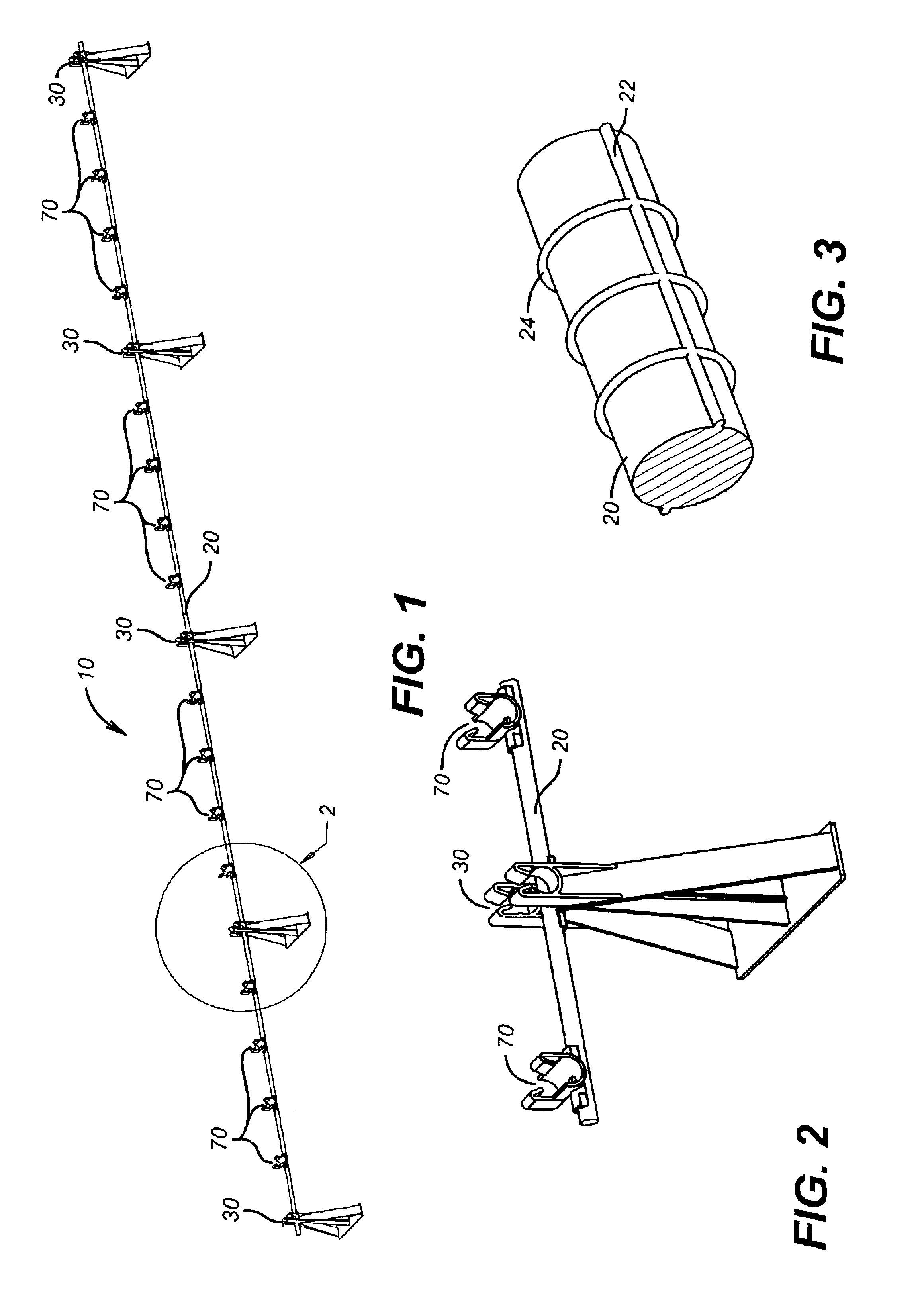
In describing the novel longitudinal bar capture and locking structures of this invention, the transverse bar chair embodiment and the transverse bar saddle clip embodiment will be described initially in connection with a new type of TBA for use at least in places where wire tying of longitudinal rebar is not favored. This facilitates economy and completeness of description, since describing the transverse bar chair and its operation in that context also describes the structure of the transverse bar chair which can be used in a standalone capacity in places where wire tying of longitudinal rods to transverse bars is permitted. In those places, the transverse bar saddle clip is not needed.

Referring to FIG. 1, a transverse bar assembly comprising apparatus of this invention for use in holding crossing reinforcing rods in position at an intersection for receiving a concrete pour is referenced generally by numeral 10. Transverse bar assembly 10 includes transverse bar 20, which is an el...


PUM

PropertyMeasurementUnit
angleaaaaaaaaaa
angleaaaaaaaaaa
temperaturesaaaaaaaaaa

Abstract

A transverse bar assembly for use in constructing rebar mats for reinforcement of concrete paving includes a plurality of chairs and clips each having a lower portion that fixes to a transverse bar in the direction of its length and an upper portion for orthogonally receiving and holding locked in place a longitudinal bar, the chair also having a support extending to a base surface.

Description

FIELD OF THE INVENTIONThis invention relates to a system for erecting a reinforcing bar lattice structure (or “rebar mat”) that is known to be used as a reinforcement and support for poured concrete in roadway construction, and more specifically to devices capable of supporting and securing longitudinal reinforcing steel rods at their designed location and spacing in such a manner as to prevent the rebar mat from being displaced from the designed position during concrete placement.BACKGROUND OF THE INVENTIONConcrete has proven to be the preferred material for the construction of roadways in many locales. In such applications, however, concrete invariably develops cracks throughout the length of the concrete structure caused by the curing process, load induced stress, weather conditions, and other causes, so that the life cycle and the ride quality of the concrete road can become severely reduced unless some means is used to prevent the concrete from separating along these crack line...

Claims


Application Information

Patent Timeline
Patent Type & Authority Patents(United States)
IPC IPC(8): E01C11/18E01C11/00E04C5/20E04C5/16
CPCE01C11/18E04C5/205E04C5/168E04C5/167
Inventor HARDY, JR., ROBERT M.WATERS, JR., LOUIS A.
Owner HARDY CONSTR TECH
Learn More