Compound engine dynamo-electric machine

Inactive Publication Date: 2005-01-11
DENSO CORP
View PDF9 Cites 23 Cited by
  • Summary
  • Abstract
  • Description
  • Claims
  • Application Information

AI Technical Summary

Benefits of technology

An object of the present invention is to provide a simple, high-performance, comfortable, compound engine-power system for a vehicle while achieving improved fuel consumption and torque. The object also involves solving problems related to cost, weight, and complexity of control as to the electro-motive assistance, and aspects related to the turbo system such as insufficient or excessive supplies of pressure depending on an increase of combustion energy as described above. The invention achieves a simple, low-power consuming, optimal

Problems solved by technology

However, the former electrical method, that is, the method of using a large capacity rotary machine, capacitor, or power converter, is troublesome because the system increases in cost, weight, and complexity.
Also, the latter mechanical method, that is, turbo supercharging, is complicated in that supercharging is insufficient at low engine speeds because the turbo system does not operate fast enough, whereas at high engine speeds, the turbo system operates too fast to the exten

Method used


Image

  • Compound engine dynamo-electric machine
  • Compound engine dynamo-electric machine
  • Compound engine dynamo-electric machine

Examples


first embodiment

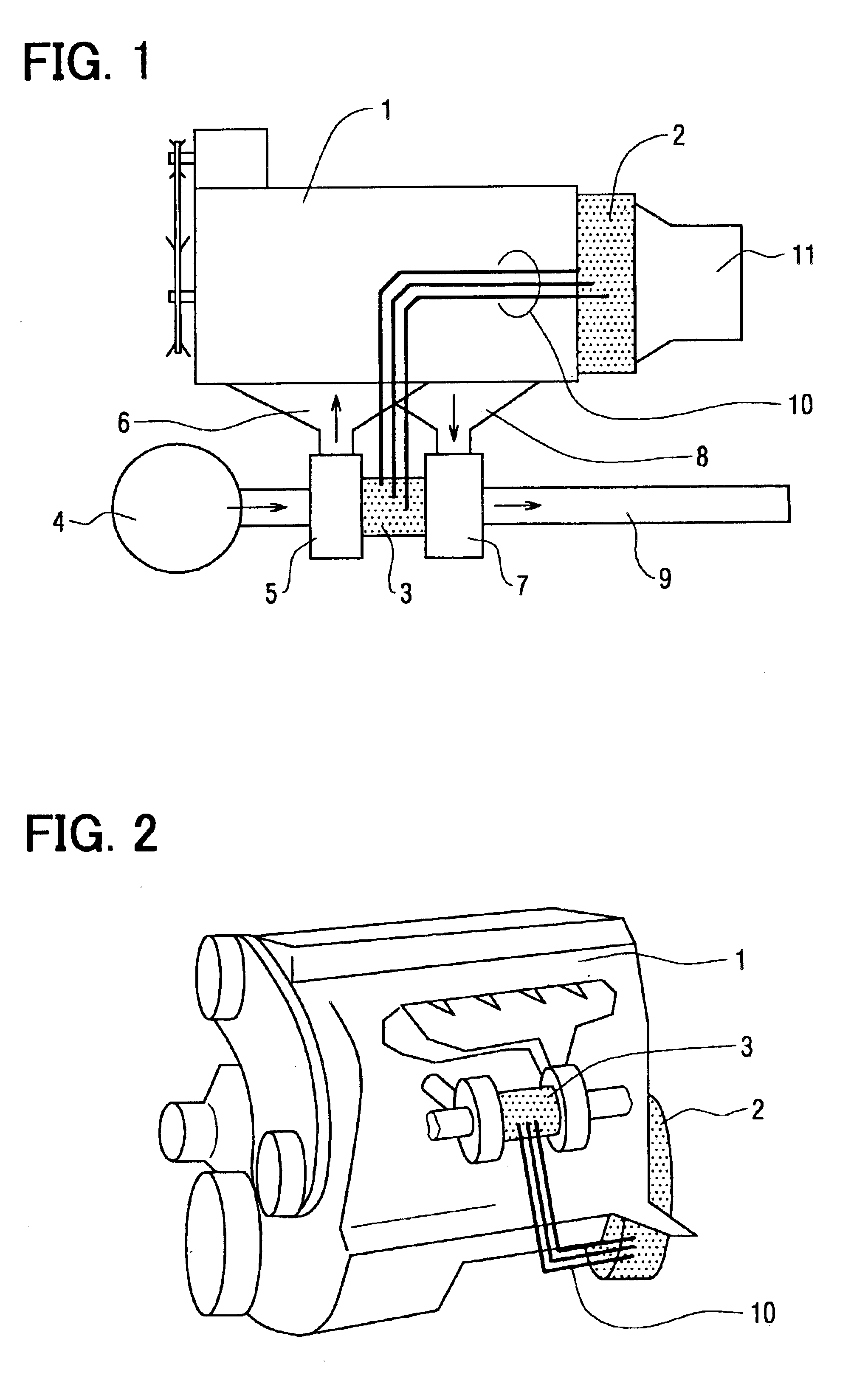
The following description, with reference to FIGS. 1 through 5, depicts an arrangement of a first embodiment of the invention as applied to a vehicular engine. The following description of the preferred embodiments is merely exemplary in nature and is in no way intended to limit the invention, its application, or uses.

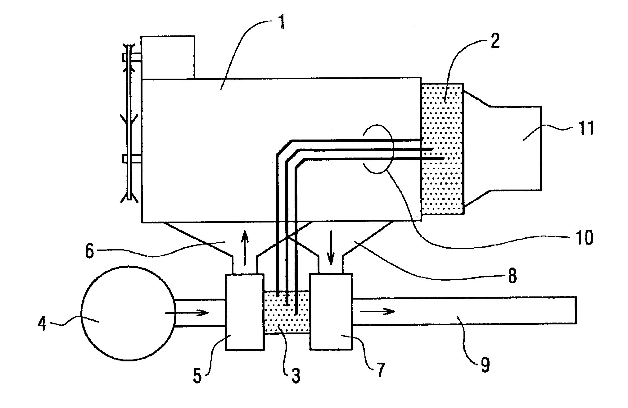
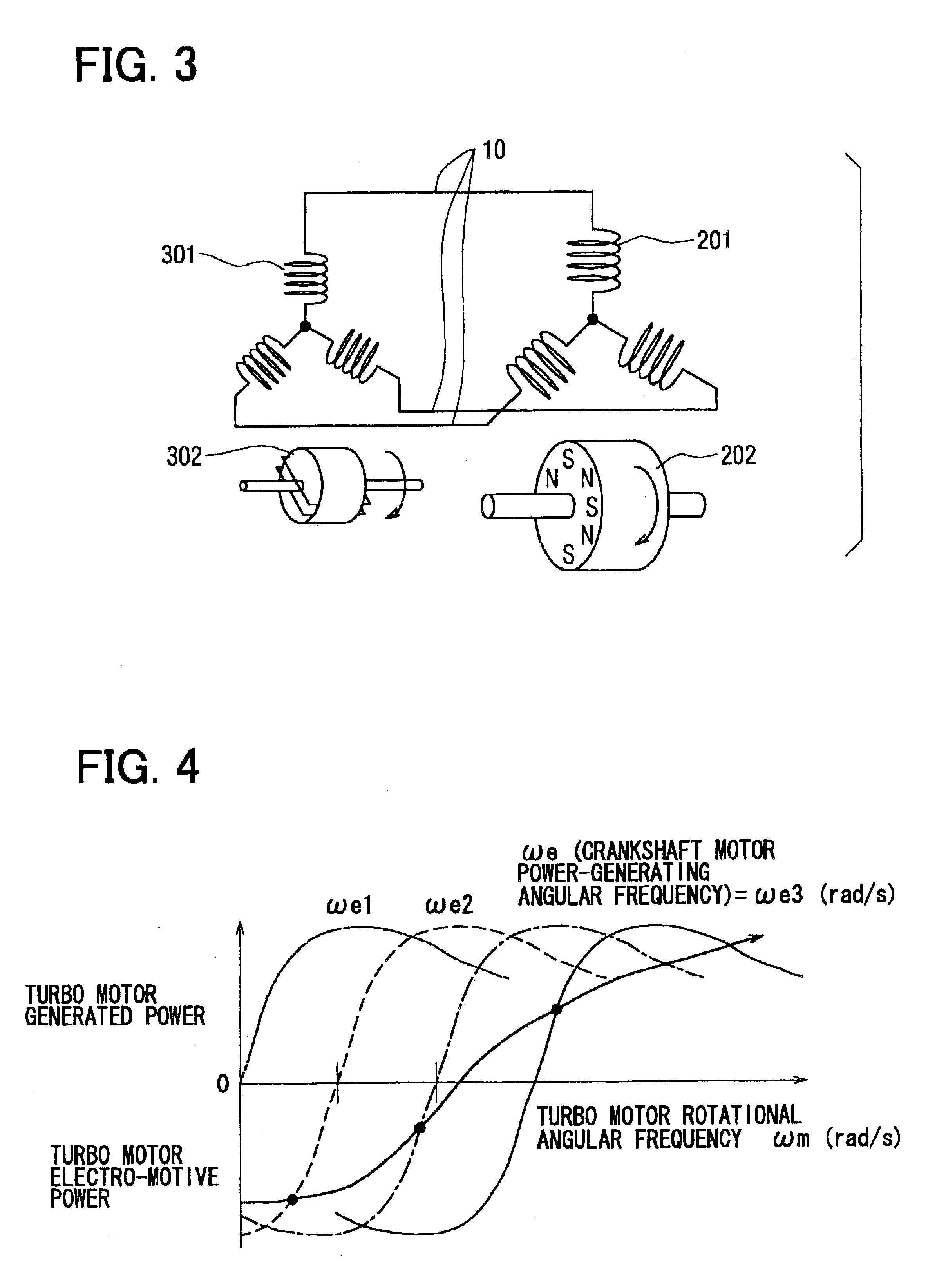
Referring to FIG. 1, a rotary machine 2 directly linked to an unillustrated crankshaft is mounted to a side surface of a multi-cylinder engine main body 1 in a space between the main body 1 and a transmission 11. The rotary machine 2 is a hybrid-polar high frequency generator motor provided with N poles and S poles formed alternately on the outer circumference of a rotor 202 by placing fifty (50) magnetic inductors with a certain space in between and then providing a magnet in each space as shown in FIG. 3. Also, the rotary machine 2 is a brushless structure provided with a field winding (not shown) placed at a stationary side and an armature winding 201 accommodated i...


PUM


Abstract

A first exhaust turbo rotary machine is able to assist turbo supercharging by operating as a motor on power generated in a second rotary machine connected to a power axis of an engine. Also, when exhaust energy is large, the first turbo rotary machine operates as a generator so as to make the second rotary machine connected to the engine motive power axis operate electrically, thereby making it possible to add exhaust energy to the engine motive power axis. Consequently, that which results is a compound engine dynamo-electric machine that improves total efficiency of the engine by adding exhaust energy, which is otherwise discarded, to the engine motive power axis. This arrangement increases engine torque in a speed region where exhaust pressure is low by utilizing part of the engine's motive power as a supercharging driving force.

Description

CROSS REFERENCE TO RELATED APPLICATIONSThis application is based upon, claims the benefit of priority of, and incorporates by reference, the contents of Japanese Patent application No. 2002-29446 filed Feb. 6, 2002, and No. 2002-172787 filed Jun. 13, 2002.BACKGROUND OF THE INVENTION1. Field of the InventionThe present invention relates to improving total fuel consumption and engine output torque of a compound system composed of an engine and a rotary machine. More particularly, the invention relates to a dynamo-electric machine or a turbo dynamo-electric machine attached to an engine that is operated in concert with another dynamo-electric machine. Finally, the invention relates to a vehicle engine usable within a broad spectrum of engine speeds and to a system of rotary machines attached thereto.2. Description of the Related ArtGenerally, many techniques have been proposed in order to improve fuel consumption and torque of engines. An example of an electrical method is generating l...

Claims


Application Information

Patent Timeline
IPC IPC(8): B60K6/04B60K6/00F02D23/00F02B37/10F02B37/00F02B39/02F02B37/04F02B39/10B60K6/44B60K6/52B60K6/543B60L50/16B60W10/06B60W20/00H02K7/18H02K19/24H02P9/04H02P9/14
CPCB60K6/24B60K6/44B60K6/46F02B37/005F02B37/10F02B39/10F02D23/00B60K6/26Y10S903/918Y02T10/6217Y02T10/623Y02T10/6295Y02T10/144Y10S903/905Y10S903/906Y10S903/916F01N5/04F02B41/10Y02T10/12Y02T10/62
Inventor KUSASE, SHIN
Owner DENSO CORP
Why Eureka
Try Eureka