Methods and devices for ablation

a technology applied in the field of epicardial mapping and ablation devices, can solve the problems of difficult manipulation of elongated and flexible endovascular ablation devices into complex geometries, insufficient visualization of endocardial anatomy and endovascular devices, and significant difficulties of endocardial ablation devices, etc., to achieve the effect of facilitating the advancement of the devi

Inactive Publication Date: 2005-01-11
ST JUDE MEDICAL ATRIAL FIBRILLATION DIV
View PDF268 Cites 246 Cited by
  • Summary
  • Abstract
  • Description
  • Claims
  • Application Information

AI Technical Summary

Benefits of technology

In still another aspect of the present invention, the device has a flexible tip which facilitates advancement of the device. The tip preferably extends for at least two inches and is free of any ablating elements. The tip is also preferably removable so that the tip also does not interfere with creating a closed loop.
In yet another aspect of the present invention, a fluid environment is created around the heart and the ablating device is submerged in the fluid environment. The fluid environment helps to ensure that no air bubbles or gaps are present and also can help to regulate the temperature by controlling the fluid temperature.

Problems solved by technology

This location creates significant difficulties for endocardial ablation devices for several reasons.
Second, the elongated and flexible endovascular ablation devices are difficult to manipulate into the complex geometries required for forming the pulmonary venous lesions and to maintain in such positions against the wall of the beating heart.
This is very time-consuming and can result in lesions which do not completely encircle the pulmonary veins or which contain gaps and discontinuities.
Third, visualization of endocardial anatomy and endovascular devices is often inadequate and knowing the precise position of such devices in the heart can be difficult, resulting in misplaced lesions.
However, on the left side of the heart where the pulmonary venous lesions are formed, thrombus can be carried by the bloodstream into the coronary arteries or the vessels of the head and neck, potentially resulting in myocardial infarction, stroke or other neurologic sequelae.
Finally, the heat generated by encdocardial devices which flows outward through the myocardium cannot be precisely controlled and can damage extracardiac tissues such as the pericardium, the phrenic nerve and other structures.

Method used


Image

  • Methods and devices for ablation
  • Methods and devices for ablation
  • Methods and devices for ablation

Examples


Embodiment Construction

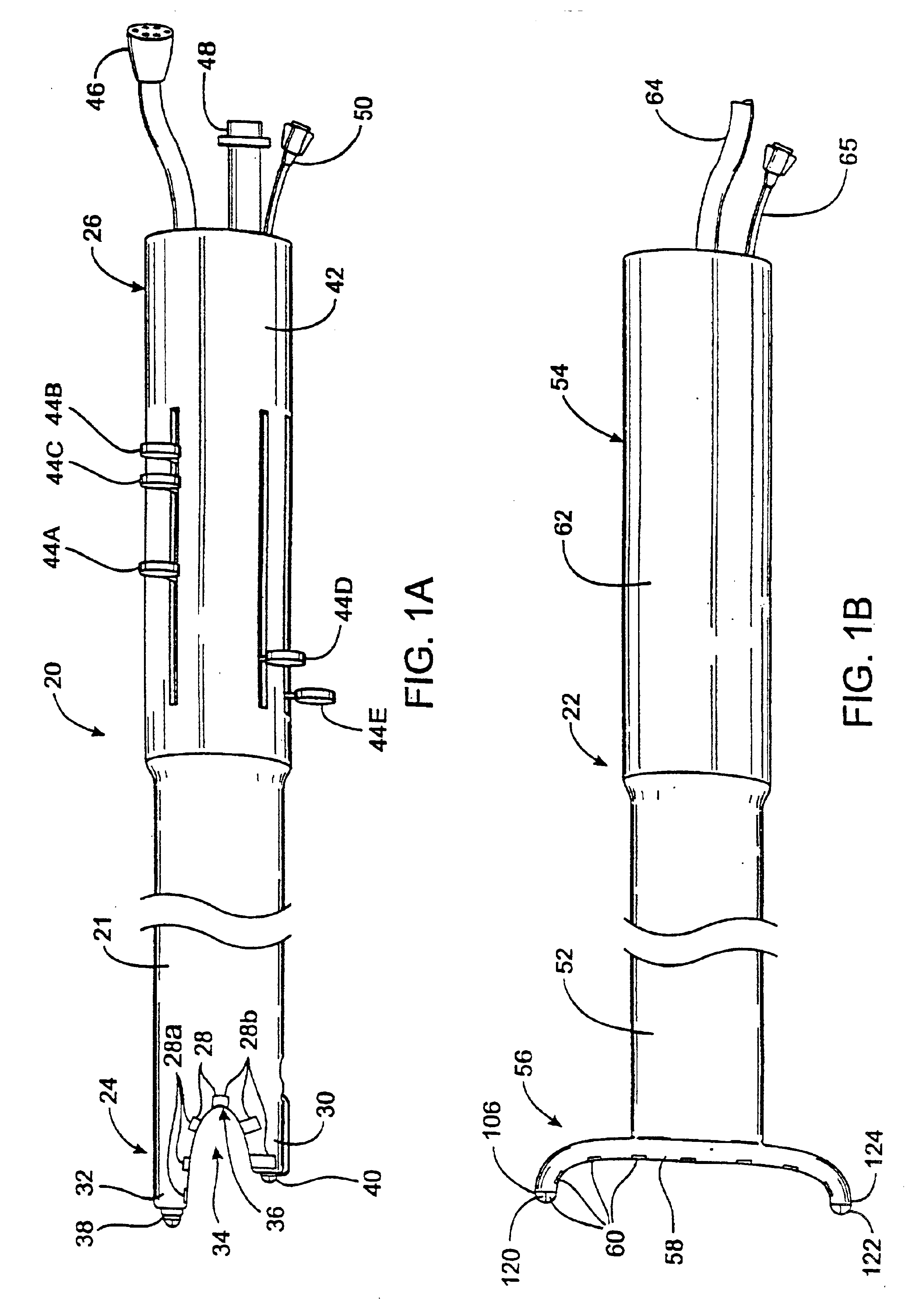
FIG. 1A-1B illustrate a first embodiment of the apparatus of the invention. In this embodiment, the apparatus comprises a left ablation probe 20, shown in FIG. 1A, and a right ablation probe 22, shown in FIG. 1B, which work in tandem to form a transmural lesion isolating the pulmonary veins from the surrounding myocardium. Left ablation probe 20 has a flexible shaft 21 extending to a working end 24 configured for insertion into the chest cavity through a small incision, puncture or access port. Opposite working end 24, shaft 21 is attached to a control end 26 used for manipulating the working end 24 from outside the chest. Shaft 21 is dimensioned to allow introduction through a small incision in the chest, preferably in a subxiphoid location, and advanced to the pulmonary veins on the posterior side of the heart. Preferably, shaft 21 is configured to be flexible about a first transverse axis to allow anterior-posterior bending and torsional flexibility, but relatively stiff about a ...


PUM


Abstract

An ablating device has a cover which holds an interface material such as a gel. The cover contains the interface material during initial placement of the device. The ablating device may also have a removable tip or a membrane filled with fluid. In still another aspect, the ablating device may be submerged in liquid during operation.

Description

BACKGROUND OF THE INVENTION1. Field of the InventionThis invention relates generally to devices and methods for ablating tissue. The diagnosis and treatment of electrophysiological diseases of the heart, and more specifically to devices and methods for epicardial mapping and ablation for the treatment of atrial fibrillation, are described in connection with the devices and methods of the present invention.2. Description of Related ArtAtrial fibrillation results from disorganized electrical activity in the heart muscle, or myocardium. The surgical maze procedure has been developed for treating atrial fibrillation and involves the creation of a series of surgical incisions through the atrial myocardium in a preselected pattern so as to create conductive corridors of viable tissue bounded by scar tissue.As an alternative to the surgical incisions used in the maze procedure, transmural ablation of the heart wall has been proposed. Such ablation may be performed either from within the ch...

Claims


Application Information

Patent Timeline
Patent Type & Authority Patents(United States)
IPC IPC(8): A61B17/22A61B18/02A61B18/00A61B18/14A61N1/06A61N7/02A61N7/00A61B17/34A61B19/00A61B5/0408A61B5/042A61B17/00A61N1/362
CPCA61B17/2202A61B17/2251A61B18/00A61B18/02A61B18/04A61B18/1402A61B18/1482A61B18/1492A61B18/18A61B18/1815A61N1/06A61N7/02A61B17/22012A61B5/0422A61N2007/0078A61B18/148A61B18/20A61B18/24A61B19/5244A61B2017/00243A61B2017/00247A61B2017/00252A61B2017/003A61B2017/22077A61B2017/2253A61B2017/3419A61B2018/00005A61B2018/00023A61B2018/0016A61B2018/00214A61B2018/00232A61B2018/00261A61B2018/00285A61B2018/00291A61B2018/00351A61B2018/00363A61B2018/00375A61B2018/00392A61B2018/00577A61B2018/00654A61B2018/00797A61B2018/00839A61B2018/00898A61B2018/00982A61B2018/1213A61B2018/142A61B2018/1467A61B2018/147A61B2018/1472A61B2018/1861A61B2018/2283A61B2019/5217A61B2019/5278A61B2019/545A61B2218/002A61B2218/007A61N1/056A61N1/362A61B34/20A61B2090/3614A61B2090/3782A61B2090/395A61N1/3629A61B5/287
Inventor SLIWA, JR., JOHN W.VASKA, MATTHIASPODMORE, JONATHAN L.ANDERSON, SCOTT C.CHAMPSAUR, GERARDCROWE, JOHN E.MORSE, STEPHEN A.MILLER, GARY HENRY
Owner ST JUDE MEDICAL ATRIAL FIBRILLATION DIV
Why Eureka
Try Eureka