Method for cleaning plasma etch chamber structures

a technology of plasma etching and chamber structure, which is applied in the direction of cleaning hollow articles, using liquids, chemistry apparatus and processes, etc., can solve the problems of affecting the surface of the chamber part, forming defects, and redistributing etched materials, and achieves a high degree of selectivity

Inactive Publication Date: 2005-01-11
MONTEREY RES LLC
View PDF22 Cites 34 Cited by
  • Summary
  • Abstract
  • Description
  • Claims
  • Application Information

AI Technical Summary

Problems solved by technology

An important issue in conventional plasma etching processes can be the redistribution of etched material.
If redistributed material is allowed to accumulate, such accumulated material can detach from chamber parts 400 and then land on a wafer, possibly forming a defect.
A drawback to a conventional method 500 can be how such a cleaning method affects chamber part surfaces.
Changes in chamber part surfaces may result in drift in an etch process, as a changing surface conditions may alter gas flows and or etch chemistry.
Further, because cleaning may consume etch chamber parts, such parts may have to be periodically replaced.
First it has been observed that such a cleaning process may result in particles remaining on chamber parts.
Thus, there may be an initial increase in particle defects following periodic maintenance of a plasma etching system.
In addition, following a conventional cleaning process such as that shown in FIG. 5, redistributed polymer material may not adhere as well to etch chamber part surfaces.

Method used


Image

  • Method for cleaning plasma etch chamber structures
  • Method for cleaning plasma etch chamber structures
  • Method for cleaning plasma etch chamber structures

Examples


third embodiment

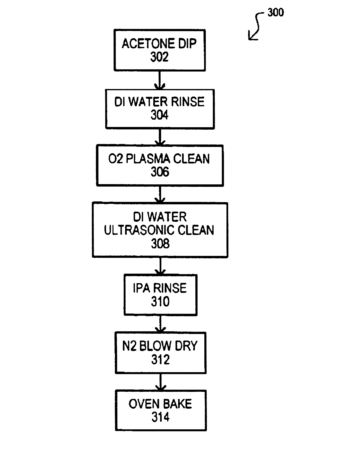
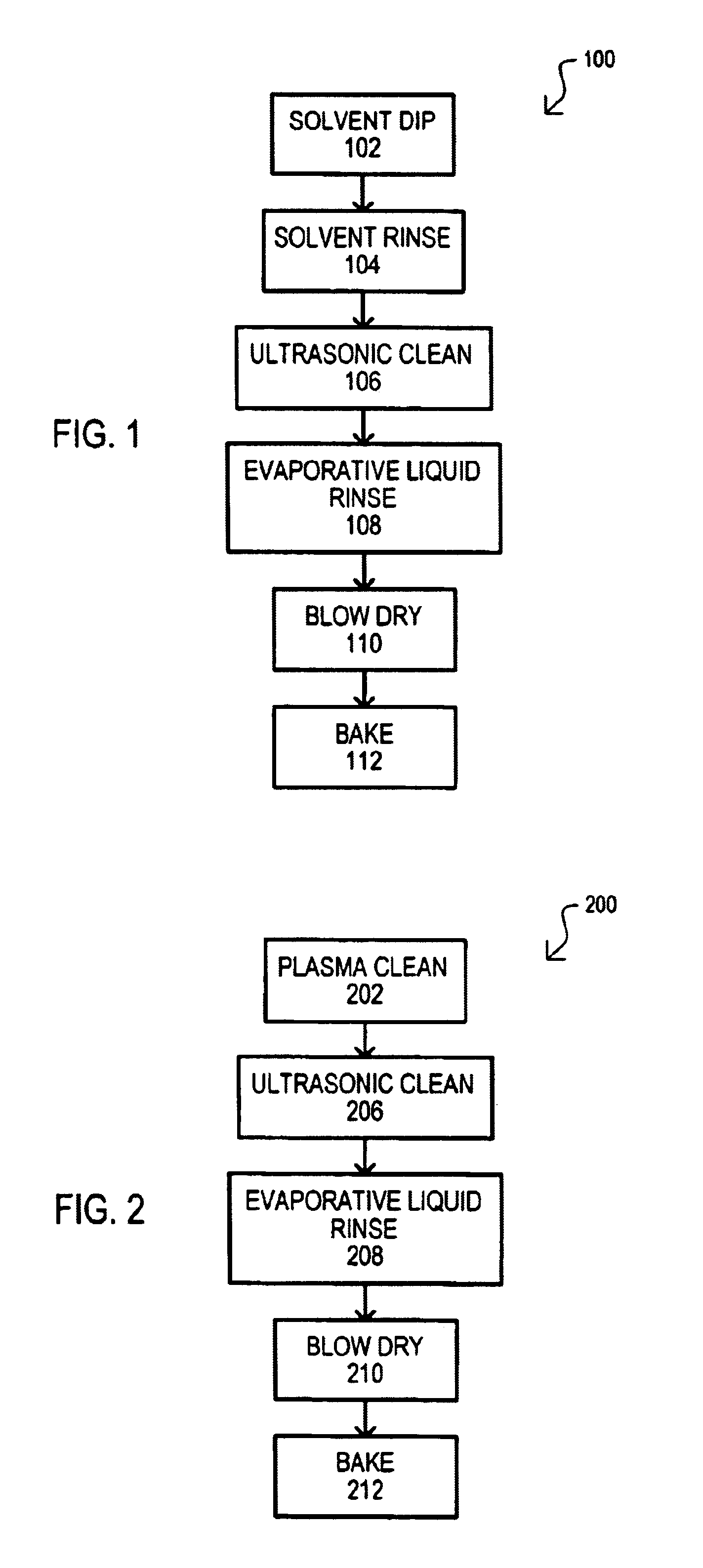
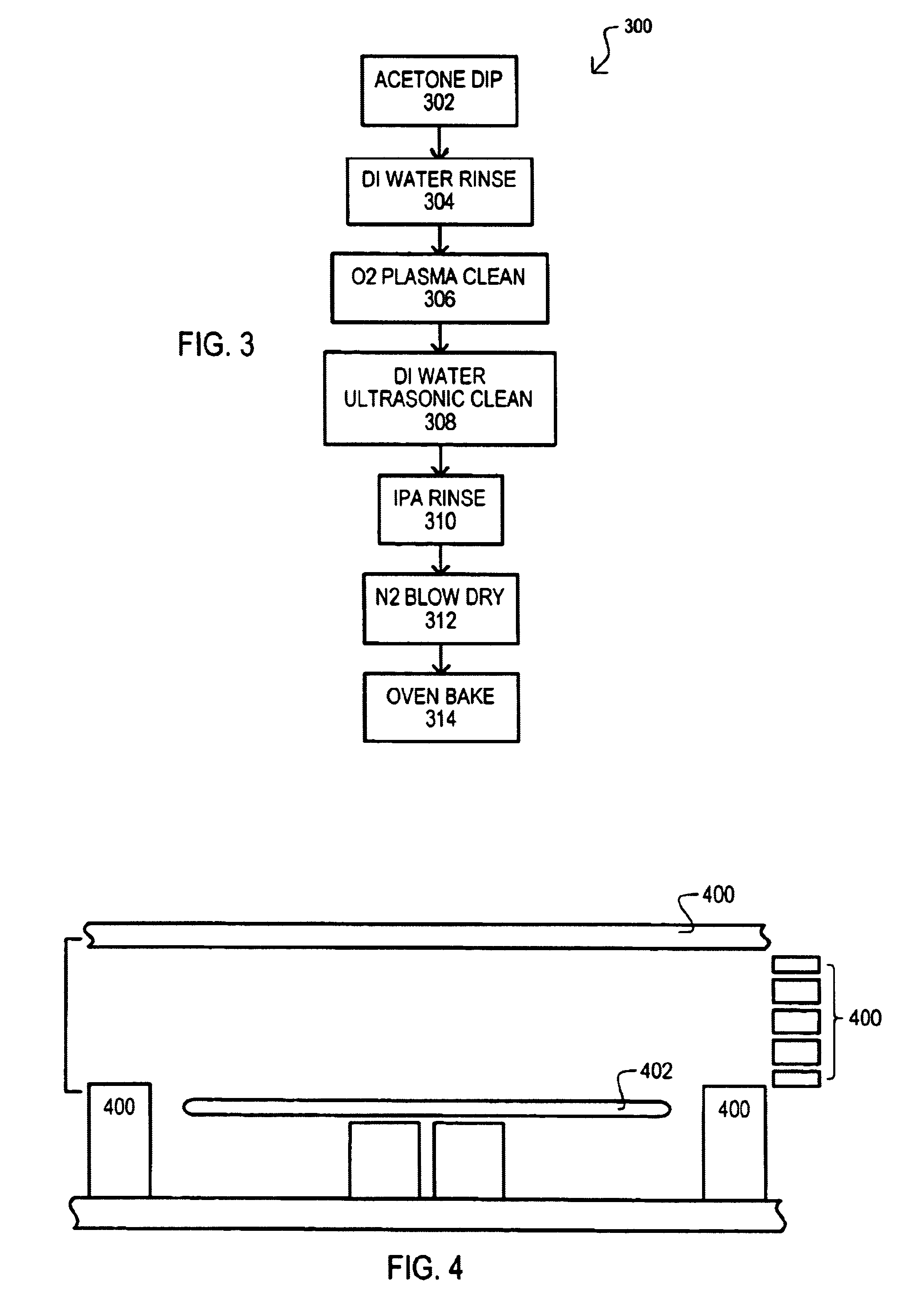
A third embodiment will now be described with reference to FIG. 3. A third embodiment may include a method of cleaning redistributed etch mask material from plasma reactor chamber parts. More particularly, a third embodiment shows method of cleaning polymer-based photoresist from quartz chamber parts used in reactive plasma etching.

A third embodiment is designated by the general reference character 300 and may include an acetone dip (step 302). Acetone dip 302 can be a photoresist polymer solvent and may dissolve redistributed photoresist polymers formed on chamber parts. A step 302 may include filling a receptacle with acetone. Quartz chamber parts may then be submerged in acetone for a period of time that may be greater than 2 hours, less than 48 hours, even more particularly from about 6-24 hours.

In this way a solvent dip may be used to remove redistributed material from plasma reactor chamber parts.

A third embodiment 300 may further include a de-ionized (DI) water rinse (step 30...


PUM

PropertyMeasurementUnit
RF) poweraaaaaaaaaa
temperatureaaaaaaaaaa

Abstract

A method for cleaning a plasma reactor clamber part (100) may include dipping the chamber part in a solvent (102) that may dissolve a material that has been redistributed on the chamber part by a reactive plasma. A chamber part may then be rinsed (104), ultrasonically cleaned (106) in a ultrasonic cleaning liquid, and then rinsed again with a liquid that may evaporate at a lower temperature than an ultrasonic cleaning liquid (108). A chamber part may then be blown dry (110) and baked (112). In addition, or alternatively, a method may also include plasma cleaning a chamber part (202).

Description

TECHNICAL FIELDThe present invention relates generally to reactive plasma systems, and more particularly to the cleaning of plasma etch reactor parts.BACKGROUND OF THE INVENTIONMost integrated circuit (IC) manufacturing processes typically include a number of manufacturing steps that can sequentially form, shape or otherwise modify various layers. One way of forming a layer can be to deposit and then etch the layer. Usually, etching can include forming an etch mask over an underlying layer. An etch mask may have a particular pattern that can mask certain portions of an underlying layer while exposing other portions. Etching can then remove portions of an underlying layer exposed by an etch mask. In this way, an etch mask pattern may be transfect to an underlying layer.Etching may include “wet” chemical etching and “dry” plasma etching. In many cases, plasma etching can provide greater controllability and greater directional control (e.g., anisotropy) if desired.An important issue in...

Claims


Application Information

Patent Timeline
Patent Type & Authority Patents(United States)
IPC IPC(8): B08B9/08B08B3/12
CPCB08B3/12H01J37/32862B08B9/08Y10S438/905
Inventor BRANCO, WALTER G.QIAO, JIANMIU
Owner MONTEREY RES LLC
Why Eureka
Try Eureka