Chromatic diffractive pigments and foils

Inactive Publication Date: 2005-01-11
VIAVI SOLUTIONS INC
View PDF63 Cites 147 Cited by
  • Summary
  • Abstract
  • Description
  • Claims
  • Application Information

AI Technical Summary

Benefits of technology

In particular, the present invention relates to chromatic (i.e., colored) multilayer diffractive pigment flakes and foils, as well as diffractive compositions which incorporate the pigment flakes. The diffractive pigment flakes and foils have diffractive structures thereon, such as a diffraction grating pattern or a holographic image pattern, which are replicated from an underlying substrate with a diffractive structure on which the flakes or foils are formed. The diffractive pigment flakes and foils can be formed with a variety of diffractive structures thereon to produce selected optical e

Problems solved by technology

However, each structure heretofore created has its limitations, such as a glittery appearance that is aesthetically undesirable for many purposes.
However, the large size of the flakes also contributes to a distinct sparkle, or “glittery” appearance.
Thick flakes also tend to pile up on one another at high angles causing loss of chroma and color variations that act as glitter.
Conventional structures and methods of producing particles with diffractive gratings thereon have rendered such particles unsuitable for achieving the optical features achievable by foil structures.
Heretofore, modifications of one structural parameter, while potentially beneficial to optical performance, inevitably have had an adverse impact on another critical characteristic.
When the particles are large, disorientation results in a glittery effect.
However, the circular grating structure is likely to suffer from very low brightness, due to the limited number of effective lines, which represent just a sub-region of very small 20 micron particles, as compared to particles of the same size having a simple linear grating type structure.
Further, Lee has no teaching as to particle thickness or groove depth and no quantification of the performance that might provide a motivation to develop an efficient or economic method to produce such complex particles.
The rougher surface detracts from the appearance and is particularly problematic in many applications, such as automotive paint.
Although a thicker top gloss coating may partially mask th

Method used


Image

  • Chromatic diffractive pigments and foils
  • Chromatic diffractive pigments and foils
  • Chromatic diffractive pigments and foils

Examples


examples

In order to quantify the color characteristics of a particular object, it is useful to invoke the L*a*b* color coordinate system developed by the Commission Internationale de l'Eclairage (CIE 1976), which is now used as a standard in the industry in order to precisely describe color values. In this system, L* indicates lightness and a* and b* are the chromaticity coordinates. The L*a*b*color system was used to generate various a*b* diagrams described in some of the following examples which plot the color trajectory and chromaticity of a selected diffractive pigment.

The L*a*b*color system allows for a comparison of the color differences between two measurements through the parameter ΔE*ab, which indicates the change in color as measured in the L*a*b* color space, such as the color difference of two different pigment designs. The numerical value for ΔE*ab is calculated through the following equation using the measured L*a*b* values:

ΔE*ab=[(ΔL*)2+(Δa*)2+(Δb*)2]1 / 2

where the symbol Δ den...

examples 1-7

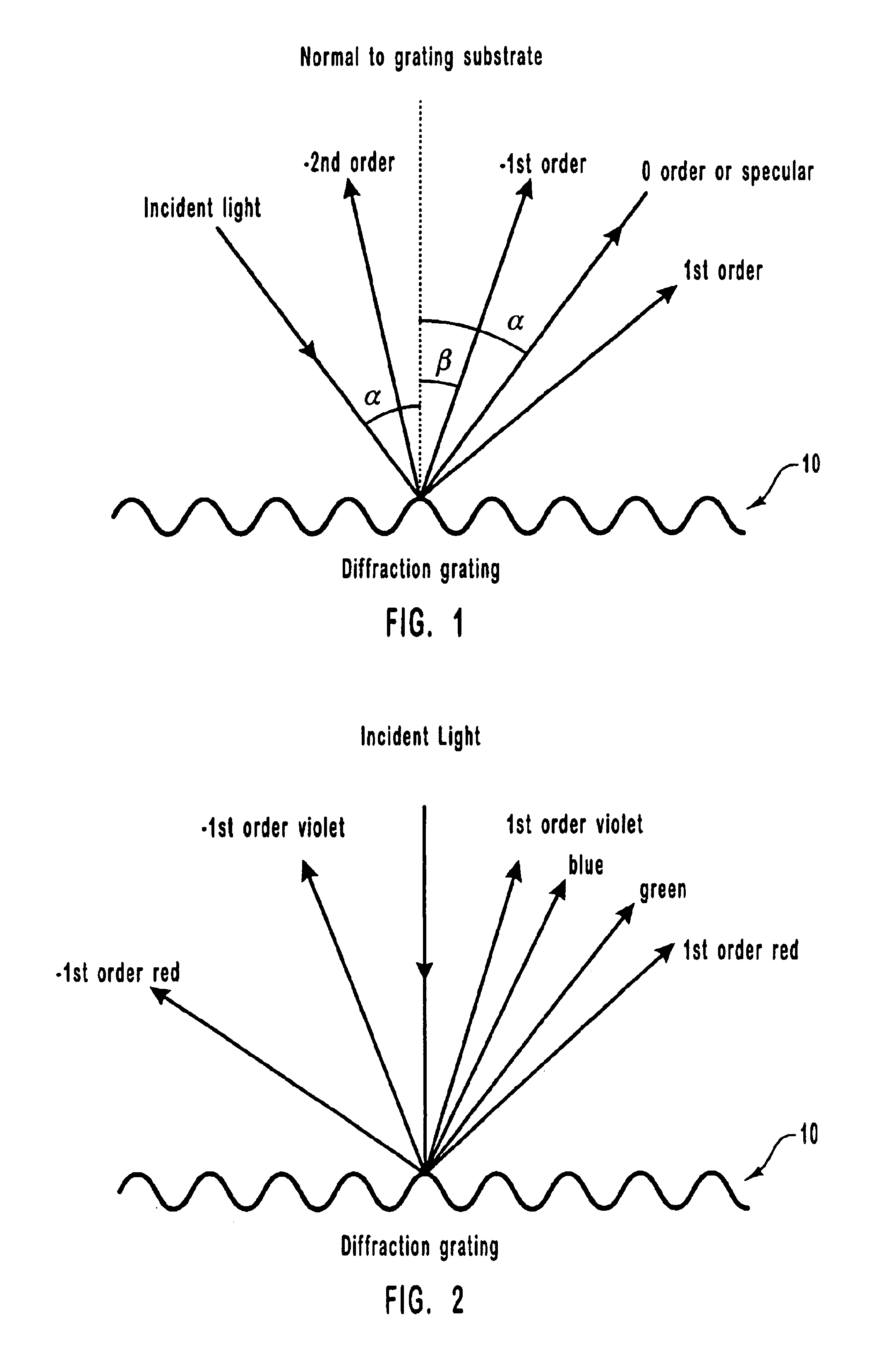
The amount of energy relative to the incident energy (efficiency) of diffractive gratings varies as a function of the type of grating and its groove depth. As a result gratings can be optimized for specific wavelengths. The light spectrum distribution in the various diffracted orders for any wavelength will be given by equation 1 set forth previously.

Various diffractive gratings (Examples 1-7) with 500 ln / mm to 3000 ln / mm were modeled using conventional optical software to determine optimal grating configurations. FIGS. 15-20 are graphs of the modeling results, showing diffraction angles as a function of various wavelengths for the various diffractive gratings of Examples 1-7. In particular, FIGS. 15-20 show the diffraction angles for various visible wavelengths (400 nm violet to 700 nm red) at normal and 45° incidence. Table 1 below sets forth the specific Example number with the corresponding Figure number and grating structure that was modeled.

TABLE 1ExampleFigureGrating Structur...

example 8

An aluminized sinusoidal diffractive grating having 1400 ln / mm was modeled using conventional optical software. FIGS. 21 and 22 are graphs showing the theoretical efficiency (percent reflectance) of the grating at various groove depths at normal and 60° incidence for 400, 550 and 700 nm wavelength light. The results of the modeling showed that a groove depth close to about 160 nm is a good compromise to get a minimum zero order and a maximum 1st order contribution, thereby enhancing the diffractive effects of the grating.

Using the same criteria, the optimum groove depth was determined to be about 220 nm for a 2000 ln / mm grating, and about 116 nm for a 3000 ln / mm grating.


PUM

PropertyMeasurementUnit
Thicknessaaaaaaaaaa
Thicknessaaaaaaaaaa
Thicknessaaaaaaaaaa

Abstract

Multilayer chromatic diffractive pigment flakes and foils are provided having diffractive structures thereon. The diffractive pigment flakes can have a symmetrical stacked coating structure on opposing sides of a reflective core layer, an asymmetrical stacked coating structure on one side of a reflective layer, or can be formed with one or more encapsulating coatings around the reflective core layer. The diffractive pigment flakes can be interspersed into liquid media such as paints or inks to produce diffractive compositions for subsequent application to a variety of objects. The foils can be laminated to various objects or can be formed on a carrier substrate. The diffractive pigment flakes and foils can be formed with a variety of diffractive structures thereon to produce selected optical effects.

Description

BACKGROUND OF THE INVENTION1. Field of the InventionThe present invention relates generally to optical effect pigments and foils. In particular, the present invention is related to chromatic diffractive pigment flakes and foils which can have a variety of diffractive structures on their surfaces to produce selected optical effects.2. Background TechnologyVarious pigments, colorants, and foils have been developed for a wide variety of applications. For example, diffractive pigments have been developed for use in applications such as creating patterned surfaces, and security devices. Diffractive patterns and embossments have wide-ranging practical applications due to their aesthetic and utilitarian visual effects.One very desirable decorative effect is the iridescent visual effect created by a diffraction grating. This striking visual effect occurs when light is diffracted into its color components by reflection from the diffraction grating. In general, diffractive gratings are essent...

Claims


Application Information

Patent Timeline
IPC IPC(8): G02B5/18G02B5/22G02B5/28
CPCG02B5/1861G03H2270/24Y10T428/25Y10T428/2993Y10T428/2982Y10T428/2991
Inventor ARGOITIA, ALBERTOPHILLIPS, ROGER W.NOFI, MICHAEL R.COOMBS, PAUL G.MARKANTES, CHARLES T.BRADLEY, JR., RICHARD A.
Owner VIAVI SOLUTIONS INC
Why Eureka
Try Eureka