Fast recovery electron multiplier

Inactive Publication Date: 2005-01-11
BIO RAD LAB INC
View PDF8 Cites 58 Cited by
  • Summary
  • Abstract
  • Description
  • Claims
  • Application Information

AI Technical Summary

Benefits of technology

The present invention is directed to an improved electron multiplier bias network that limits the response of the multiplier when the multipl

Problems solved by technology

For input signals near the upper end of the linear range of an electron multiplier, the electron multiplier can only maintain the large output signal until the loss of electrons from the dynodes and their associated capacitors causes the voltage on the dynodes to change significantly; this, in turn, causes the gain of the multiplier to change.
The long time required to recover from charge depletion induced non-linearity limits the utility of electron multipliers in situations where small signals-of

Method used


Image

  • Fast recovery electron multiplier
  • Fast recovery electron multiplier
  • Fast recovery electron multiplier

Examples


Embodiment Construction

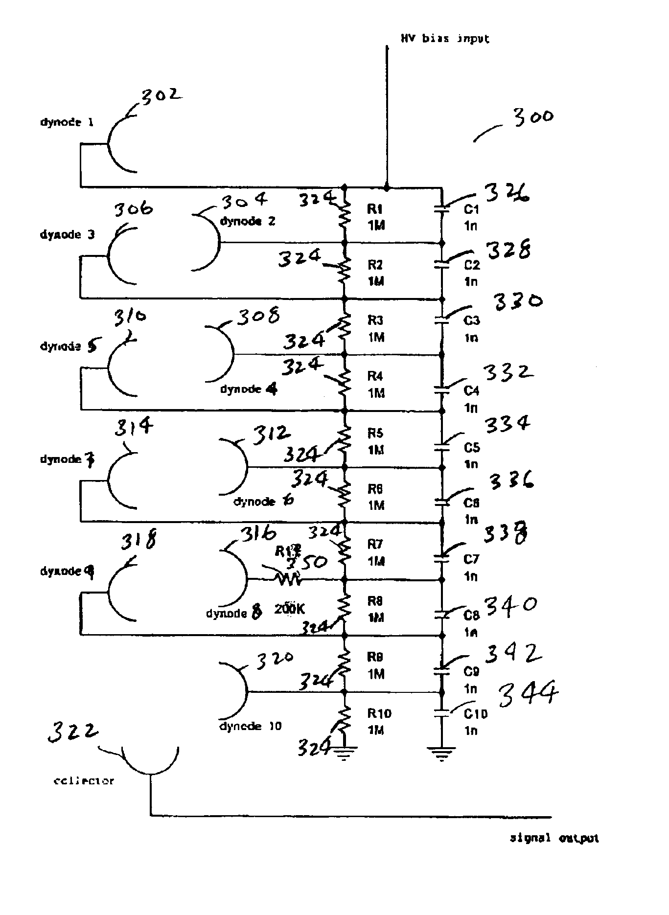
Embodiments of the present invention are directed towards modifications of an electron multiplier's bias network that limit the response of the multiplier when the multiplier is faced with an input signal larger than the upper limit of the range of interest, and also permit the electron multiplier to recover fully and rapidly when the large input signal ends. Rapid recovery allows the detector to be used to measure small signals that occur shortly after the out-of-range signal ends. Limiting the response of the electron multiplier to out-of-range input signals has the added benefit of increasing the lifetime of the detector by decreasing the gain of the multiplier during out-of-range signals. The following terms are used herein, namely: in-range signal; out-of-range signal; and saturating signal to describe different ranges of input signals. An in-range signal is one that is within the linear range of the electron multiplier. An out-of-range signal is a signal that is larger than th...


PUM


Abstract

An improved electron multiplier bias network that limits the response of the multiplier when the multiplier is faced with very large input signals, but then permits the multiplier to recover quickly following the large input signal. In one aspect, this invention provides an electron multiplier, having a cathode that emits electrons in response to receiving a particle, wherein the particle is one of a charged particle, a neutral particle, or a photon; an ordered chain of dynodes wherein each dynode receives electrons from a preceding dynode and emits a larger number of electrons to be received by the next dynode in the chain, wherein the first dynode of the ordered chain of dynodes receives electrons emitted by the cathode; an anode that collects the electrons emitted by the last dynode of the ordered chain of dynodes; a biasing system that biases each dynode of the ordered chain of dynodes to a specific potential; a set of charge reservoirs, wherein each charge reservoir of the set of charge reservoirs is connected with one of the dynodes of the ordered chain of dynodes; and an isolating element placed between one of the dynodes and its corresponding charge reservoir, where the isolating element is configured to control the response of the electron multiplier when the multiplier receives a large input signal, so as to permit the multiplier to enter into and exit from saturation in a controlled and rapid manner.

Description

BACKGROUND OF THE INVENTIONThe present invention relates to electron multipliers. More specifically, the present invention is related to electron multipliers used as detectors for time-of-flight mass spectrometry.Electron multipliers are often utilized as detectors for time-of-flight mass spectrometry. There are two types of electron multipliers: discrete dynode electron multipliers and continuous dynode electron multipliers. Discrete dynode multipliers generally consist of a cathode; a series of dynodes, shaped plates or assemblies of plates; and an anode connected together by a chain of resistors. A high voltage is applied across the chain to create a potential difference between each pair of dynodes that drives secondary electrons down the dynode chain to the anode.In an electron multiplier, an ion or other particle striking the cathode will produce secondary electrons that are accelerated to the first dynode. Upon striking the first dynode, these electrons generate another set o...

Claims


Application Information

Patent Timeline
IPC IPC(8): H01J43/00H01J29/52H01J43/18H01J43/30
CPCH01J43/30H01J43/20
Inventor KELLER, CRAIG A.PLOWS, FIONA L.
Owner BIO RAD LAB INC
Why Eureka
Try Eureka