
Low-to-high voltage conversion method and system

a low-to-high-voltage conversion and low-to-high-voltage technology, applied in logic circuits, logic circuit coupling/interface arrangements, pulse techniques, etc., can solve problems such as short circuits, static current drawn by high-voltage circuits, and problems such as problems, to achieve the effect of less delay and lower power consumption

Inactive Publication Date: 2005-01-11
FUJITSU LTD
View PDF36 Cites 30 Cited by
  • Summary
  • Abstract
  • Description
  • Claims
  • Application Information

AI Technical Summary

Benefits of technology

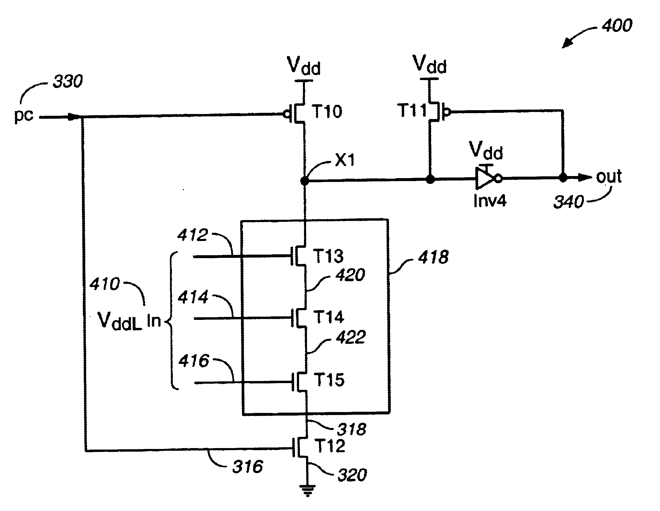
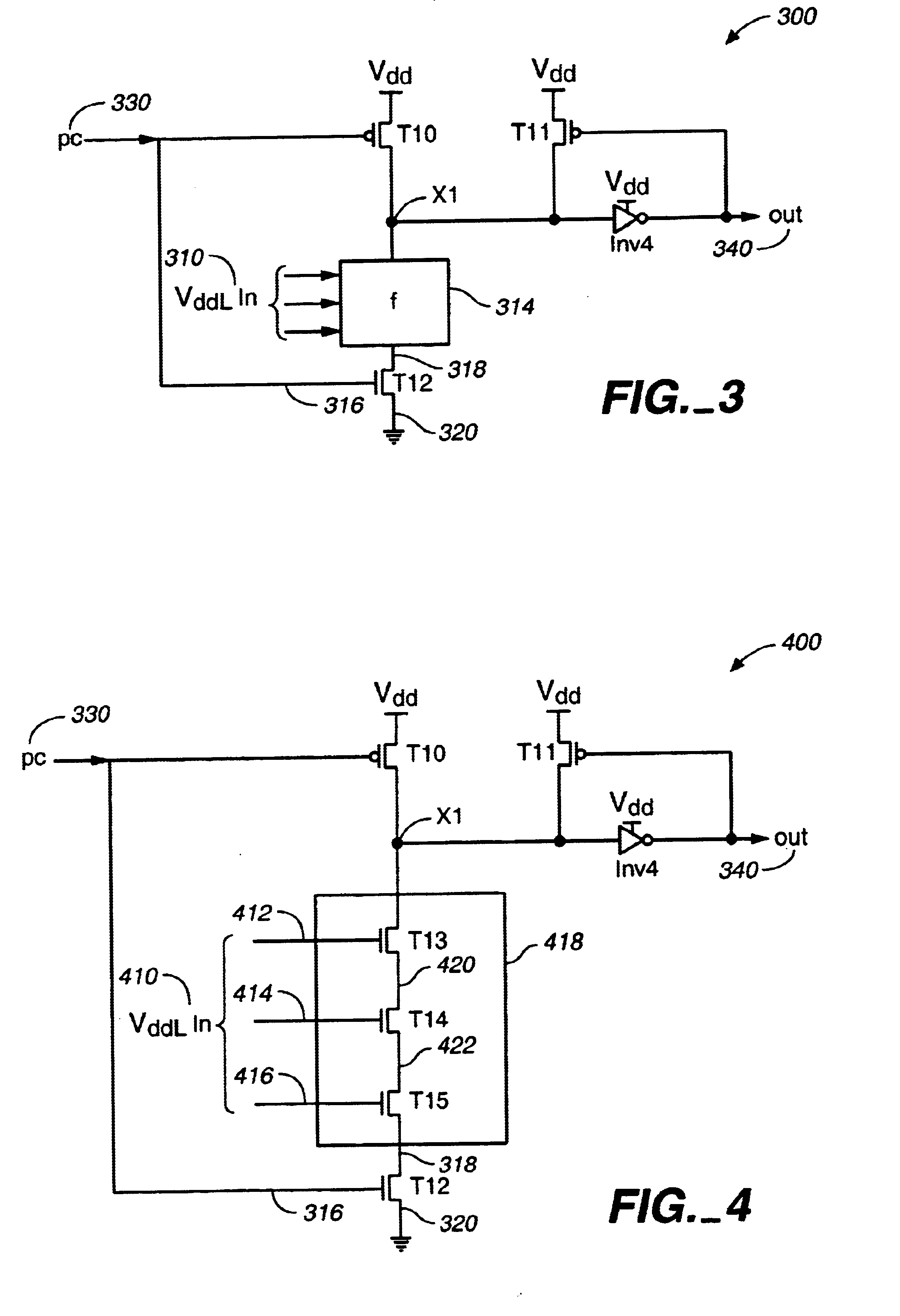
The present invention provides a system and method for converting a voltage input from a low voltage source to a voltage output at a high voltage source using a domino logic circuit design. In one aspect of the invention the domino logic gates, using a low voltage source, are connected to domino logic gates using a high voltage source without need for a separate, i.e., explicit, low-to-high voltage converter circuit. Another aspect is that there is little or no static current loss at quiescent time from the logic gates using the multiple voltage sources. Yet another aspect is that there is less delay and lower power consumption than conventional low-to-high voltage converter circuits.

Problems solved by technology

However, high voltage circuits draw static current when driven by low voltage signals.
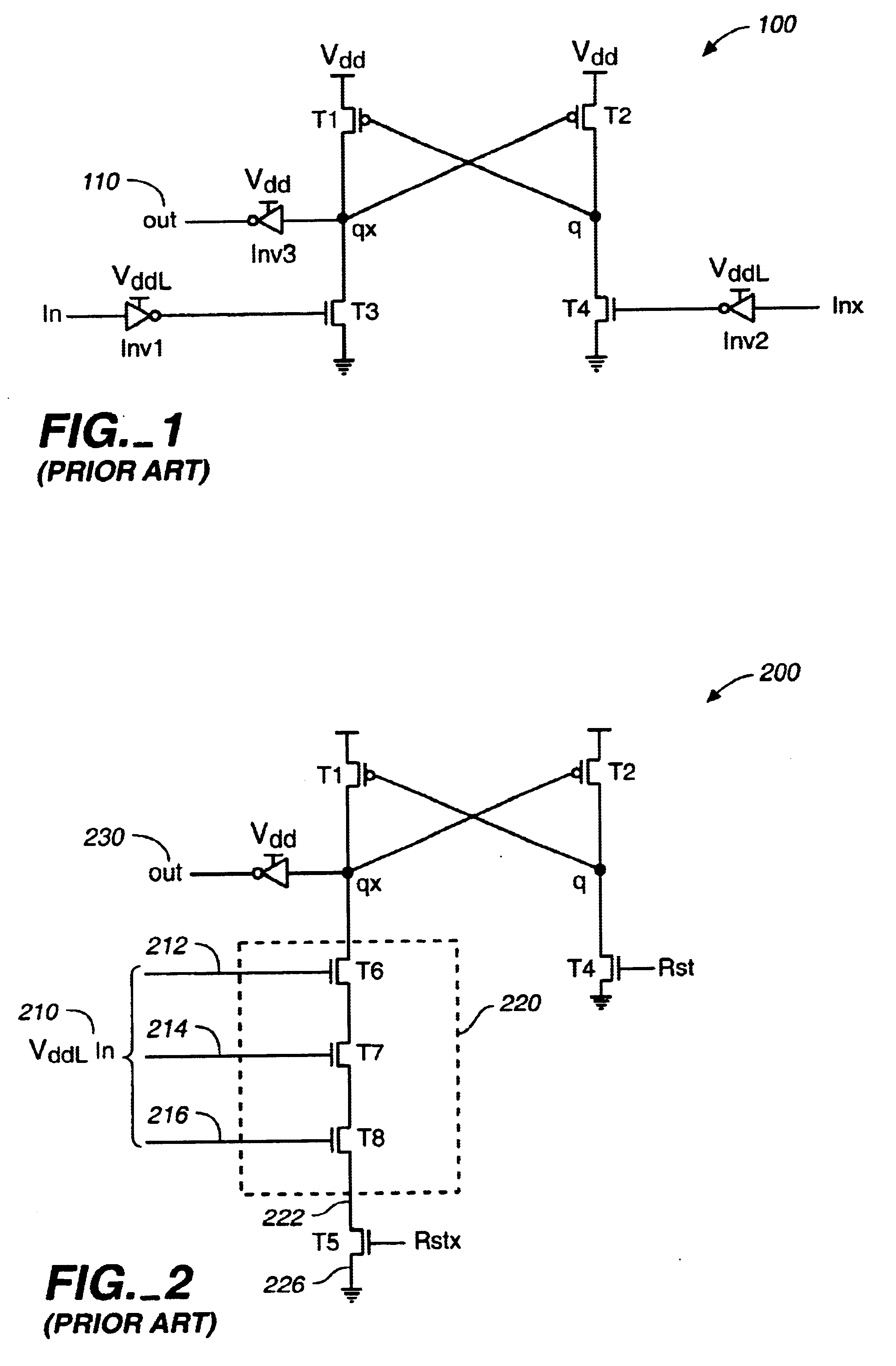
Although the above simple voltage converter 100 eliminates or nearly eliminates static current in the Boolean logic circuits at quiescent time, i.e., when the inputs are stable, problems occur when the converter 100 switches.
There is short circuit current during the transitions, and there is a delay because the switching is only completed when both q and qx have switched.
This voltage converter circuit 200 has the same disadvantage as the voltage converter 100 of FIG. 1 in that there is short circuit current during reset, e.g., qx switches from ‘1’ to ‘0,’ and during evaluation (Rstx=‘1’), e.g., q switches from ‘1’ to ‘0.’ There is also a time delay as in the circuit of FIG. 1, because switching is not completed until both q and qx switch.

Method used


Image

  • Low-to-high voltage conversion method and system
  • Low-to-high voltage conversion method and system
  • Low-to-high voltage conversion method and system

Examples


second embodiment

FIG. 7 is a schematic of a low-to-high voltage converter with a Boolean function according to the present intention. FIG. 7 is similar to FIG. 3 except that nMOS transistor T12 has been removed and nMOS pull-down circuit 718 is connected directly to ground 720. One example of a use of circuit 700 is in a second-stage domino circuit following circuit 300 of FIG. 3. For proper operation, circuit 700 must have the voltage inputs, i.e., VddL In 710, e.g., inputs 712, 714, and 716, set to ‘0’ during the precharge stage, where one or more of input signals VddL In 710 is set by low voltage supply VddL. FIG. 7 is called a footless domino circuit, because the foot switch transistor T12 is missing.

FIG. 8 is a simplified timing diagram of the input pc 730, and inputs 712, 714, and 716 of FIG. 7. The simplified timing diagram shows three stages: a precharge stage 810 followed by an evaluate stage 112, and followed by another precharge stage 814. During the first precharge stage 810, pc 730 and ...

third embodiment

FIG. 9 is a schematic diagram of a low-to-high voltage converter of the present invention for implementing a Boolean function comprising one or more logic gates. FIG. 9 is similar to FIG. 3 except the keeper circuit 920 (i.e., transistor T11 connected to inverter Inv4) is optional, and node X1 is connected to a CMOS gate 910, then to output out 912, rather than to Inv4, then to out 340. The CMOS gate 910 may be a NAND gate, a NOR gate, an inverter, or other logic gate. As node X1 is set by Vdd, the CMOS gate can be part of a subsequent high voltage logic circuit.

Some of the advantages of the low-to-high voltage converter circuits of FIGS. 3, 4, 7, and 9 over the prior art include: 1) a reduction in short circuit current during switching; 2) a shorter delay; and 3) low and high voltage precharge gates can be interchanged in a domino style without the need of any special low-to-high voltage converter circuit.

To illustrate the above third advantage of the interchanging of low and high ...


PUM


Abstract

A system and method, for converting a voltage input from a low voltage source to a voltage output at a high voltage source using a domino logic circuit design. An embodiment provides a low to high voltage conversion system. The system includes: a pull-up transistor coupled to a high voltage source for charging a node, when a precharge signal is received; a low voltage source used for setting an input voltage; a pull-down network for discharging the node depending, at least in part, on the input voltage; and an output voltage determined from the node.

Description

FIELD OF THE INVENTIONThe invention relates generally to the field of circuit design, and in particular to a method and system for Low-to-High voltage conversion in an electronic circuit.BACKGROUND OF THE INVENTIONWhile low power consumption in a digital circuit design is a desirable design goal, its importance has increased in today's market where many consumer devices, e.g., cell phones, digital cameras, laptops, Personal Digital Assistants (PDAs), and games, depend upon batteries to supply power. One conventional technique is to use different supply voltage sources in a circuit. For example, the part of the circuit that needs high performance uses one supply voltage, while the rest of the circuit uses a lower supply voltage to reduce power consumption.However, high voltage circuits draw static current when driven by low voltage signals. For example, a pMOS transistor connected to a high voltage supply is typically turned off when the gate of the transistor has a voltage approxima...

Claims


Application Information

Patent Timeline
Patent Type & Authority Patents(United States)
IPC IPC(8): H03K19/0185
CPCH03K19/01855
Inventor TZARTZANIS, NESTORWALKER, WILLIAM W.
Owner FUJITSU LTD
Learn More