Antenna arrays formed of spiral sub-array lattices

a spiral sub-array and spiral technology, applied in the structural form of individual energised antenna arrays, resonant antennas, radiating elements, etc., can solve the problems of array antennas not without disadvantages, destructive addition of electromagnetic fields, etc., to reduce the side lobe of radiation pattern, widen the antenna bandwidth, and the effect of increasing the spacing of elements

Inactive Publication Date: 2005-01-11
HARRIS CORP
View PDF27 Cites 265 Cited by
  • Summary
  • Abstract
  • Description
  • Claims
  • Application Information

AI Technical Summary

Benefits of technology

The present invention advantageously teaches an array antenna comprising a plurality of sub-arrays, wherein the antenna elements of each sub-array are arranged in an aperiodic spiral configuration. In one embodiment the spiral configuration can be Archimedean, logarithmic, or another configuration where the boundaries of the sub-array approximate a circle. In other embodiments, to support the optimal geometric combination of the sub-arrays, sub-arrays based on a square, octagon or polygon can be used. The special case represented by a single sub-array is further included within the scope of the present invention. These shapes further allow the formation of array configurations that are three-dimensional and offer desired spatial coverage characteristics. Foe example, a pyramidal array configuration can be constructed with four polygonal sides and a square top. A cubic array can be constructed with four square sides

Problems solved by technology

To provide a directive array antenna radiation pattern, the elemental fields add constructively in the desired direction and add destructively in those directions where no signal is desired.
However, array antennas are not without disadvantages.
Squeezing the feed network into the small space between the elements presents difficult design and manufacturing challenges, resulting in an expensive feed network, and expensive, miniaturized element-level electronics (often referred to as element modules).
Bandwidth limitations and mutual coupling between closely-spaced elements and their feeds also present disadvantages.
It is also difficult to provide dual or multi-beam operation within an array antenna due to these various antenna element spacing issues.
The element periodicity (i.e., the distance between individual elements of the sub-array) is established to produce the desired antenna operational characteristics,

Method used


Image

  • Antenna arrays formed of spiral sub-array lattices
  • Antenna arrays formed of spiral sub-array lattices
  • Antenna arrays formed of spiral sub-array lattices

Examples


Embodiment Construction

The present invention will now be described more fully hereinafter with reference to the accompanying drawings, in which preferred embodiments of the invention are shown. This invention may, however, be embodied in many different forms and should not be construed as limited to the embodiments set forth herein. Rather, these embodiments are provided so that this disclosure will be thorough and complete, and will fully convey the scope of the invention to those skilled in the art. Like numbers refer to like elements throughout.

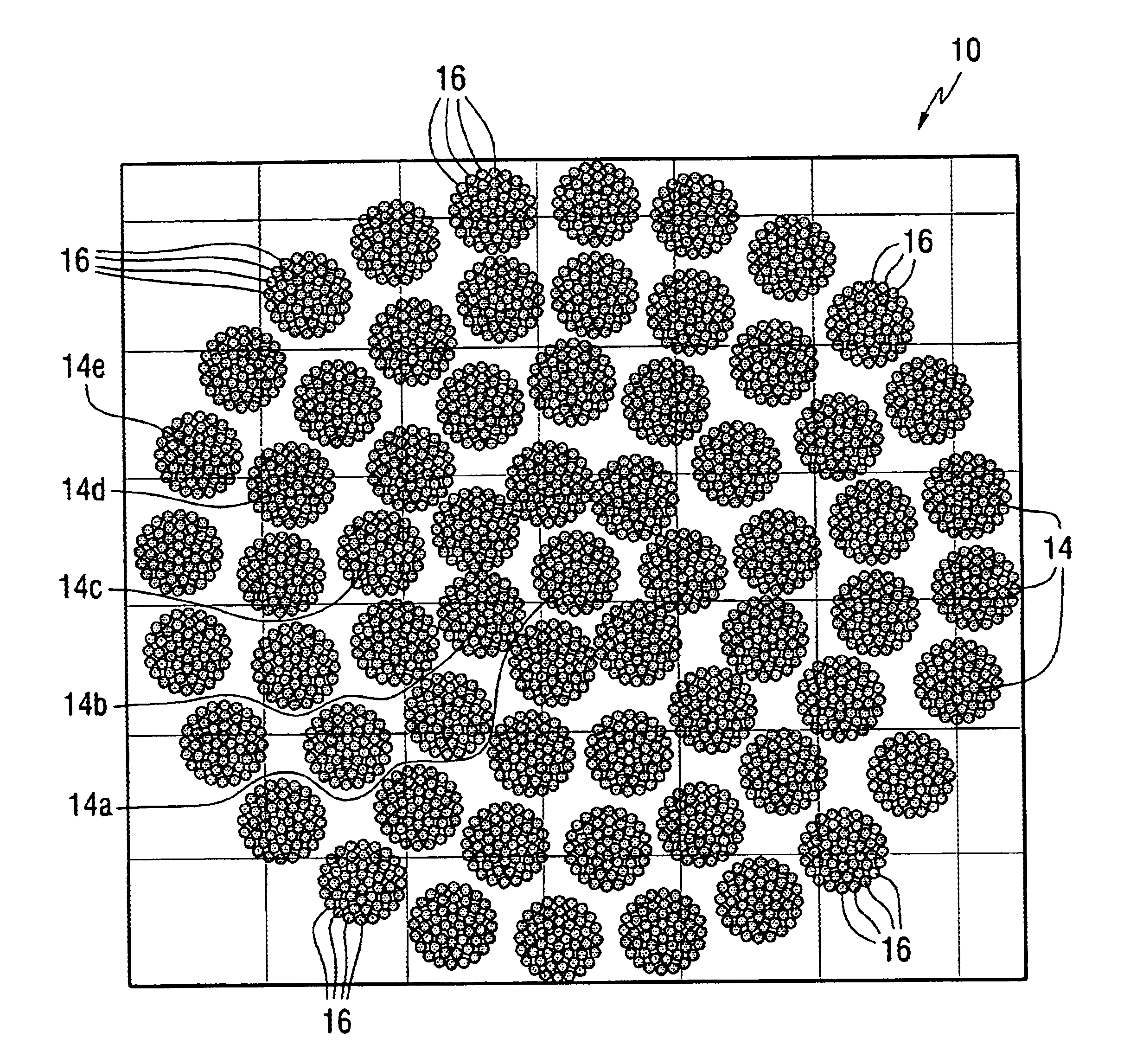
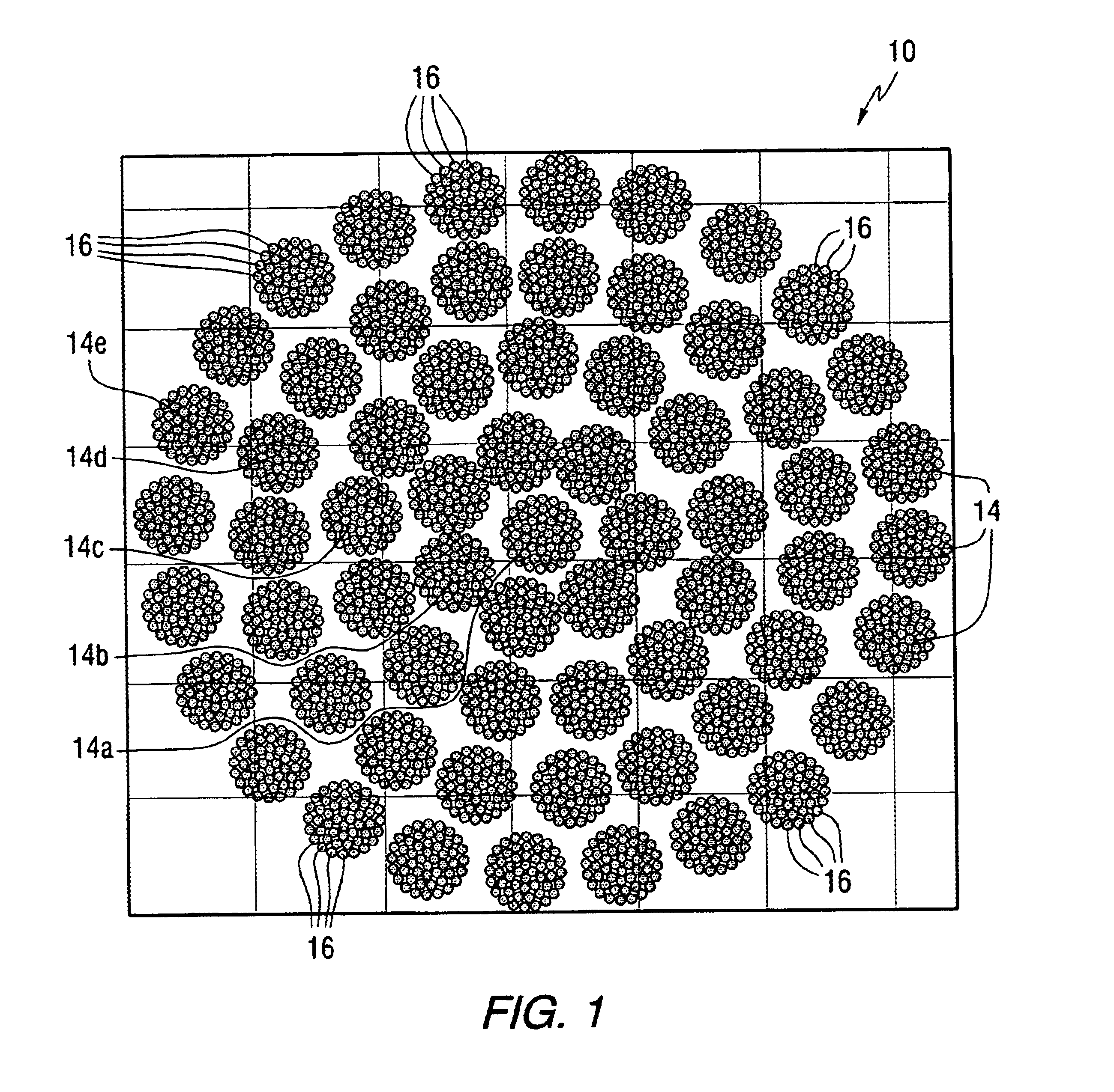
FIG. 1 illustrates an array antenna 10 of the co-pending, commonly-owned patent application, comprising a plurality of preferably identical aperiodic sub-arrays 14, where antenna elements 16 of each aperiodic sub-array 14 are configured in concentric circles as shown. The sub-arrays 14 are then aperiodically arranged to form the array antenna 10. The array antenna 10 can be a two or three dimensional structure, for example a polygon, a cube, other polygonal thre...


PUM


Abstract

A antenna array (20) includes a plurality of periodic or aperiodic arranged sub-arrays (22). Each sub-array (22) includes a plurality of antenna elements (32) arranged in the form of a spiral (30). The sub-arrays (22) can comprise various spiral shapes to provide the required physical configuration and operational parameters to the antenna array (20). The elements (32) of each sub-array (22) are arranged to minimize the number of such elements (32) that intersect imaginary planes perpendicular to the spiral and passing through the spiral center. Such an orientation of the elements (32) minimizes grating lobes in the antenna pattern.

Description

FIELD OF THE INVENTIONThis invention relates generally to the field of antenna arrays, and more particularly, this invention relates to antenna arrays formed from a single or a plurality of spiral subarray lattices.BACKGROUND OF THE INVENTIONTypically, the radiation pattern of a single element antenna is relatively wide and the gain (directivity) is relatively low. High gain performance can be achieved by constructing the antenna with a plurality of individual antenna elements in a geometrical and electrical array. These array antennas (or simply arrays) are typically used for applications requiring a narrow beamwidth high-gain pattern (i.e., low energy in the beam side lobes) and the ability to scan over a relatively wide azimuth region. Low side-lobe antennas are especially advantageous for satellite communications and scanning radars.The individual antenna elements in the array are usually identical, although this is not necessarily required, and may comprise any antenna type, e....

Claims


Application Information

Patent Timeline
IPC IPC(8): H01Q3/26H01Q21/22H01Q21/00H01Q21/06
CPCH01Q3/26H01Q21/22H01Q21/061H01Q21/0087
Inventor PHELAN, HARRY RICHARDGOLDSTEIN, MARK LAWRENCE
Owner HARRIS CORP
Why Eureka
Try Eureka