
Electrophoretic dispersion, electrophoretic device, and electronic device

a technology of electrophoretic devices and electrophoretic particles, applied in the direction of optics, instruments, optical elements, etc., can solve the problems of difficult to control the density of electrophoretic particles with preciseness, difficult to control the number and volume of cavities, and settle the electrophoretic particles

Inactive Publication Date: 2005-01-11
SEIKO EPSON CORP
View PDF10 Cites 12 Cited by
  • Summary
  • Abstract
  • Description
  • Claims
  • Application Information

AI Technical Summary

Benefits of technology

The present invention has been made in order to solve the above problems. It is an object of the present invention to provide an electrophoretic dispersion in which the settlement of electrophoretic particles is prevented, wherein the electrophoretic particles have a density precisely controlled by a simple method.
It is another object of the present invention to provide an electrophoretic device that includes the electrophoretic dispersion, in which the settlement of electrophoretic particles is prevented, and that can display a stable image for a long period.
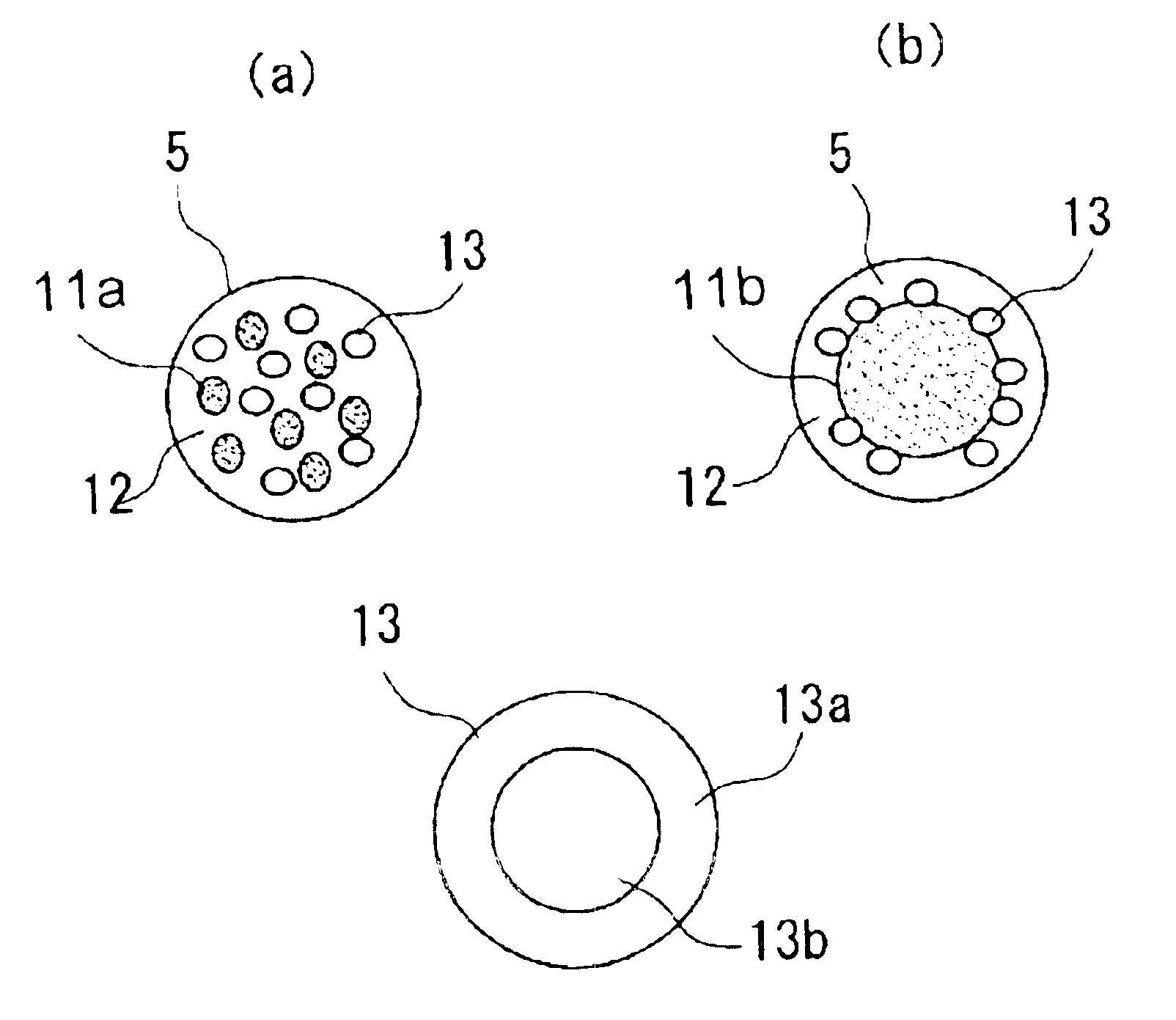
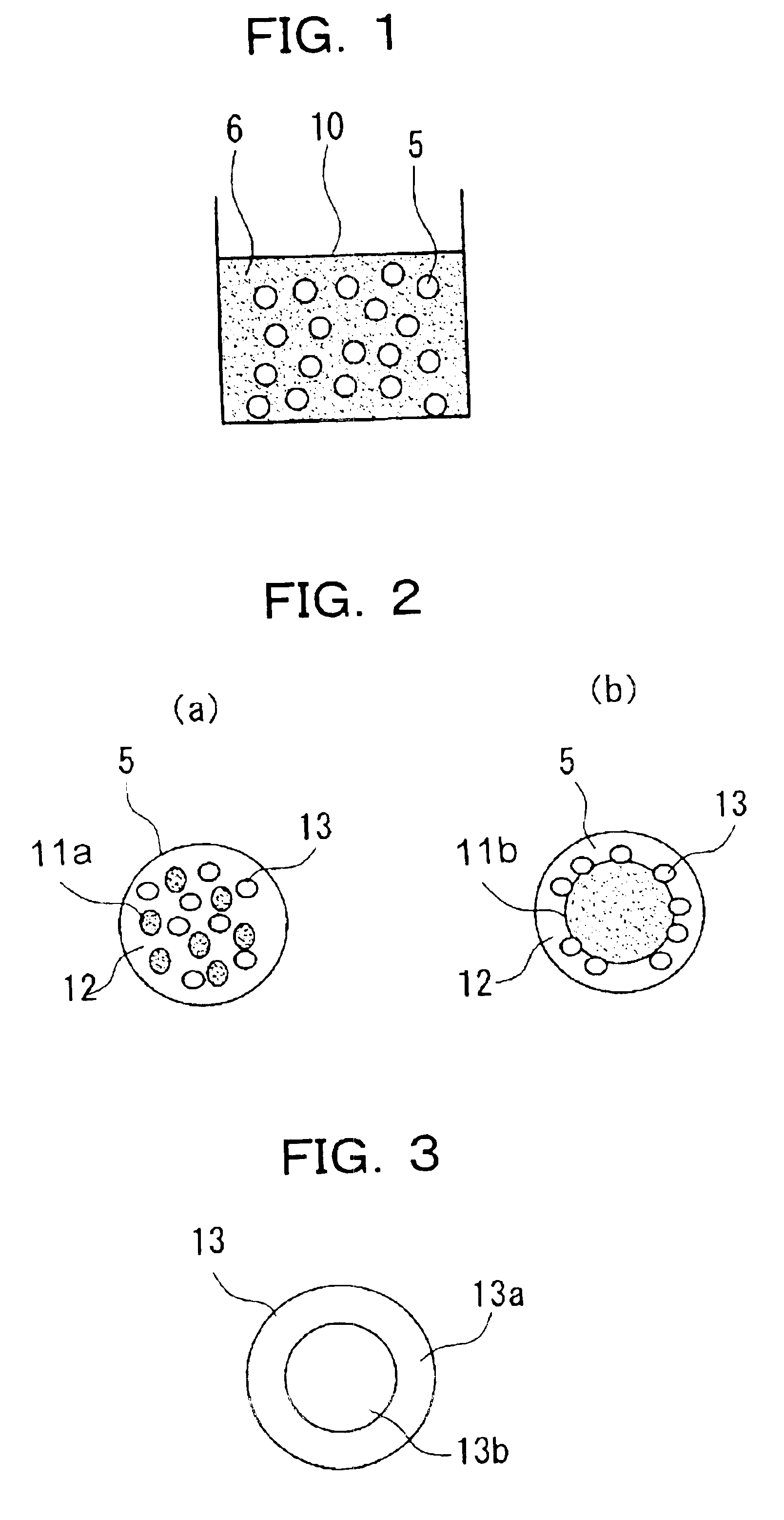
According to the present invention, the content of the hollow microcapsules can be controlled and / or the number of the hollow microcapsules contained in the electrophoretic particles can be controlled to precisely adjust the density of the electrophoretic particles in a simple manner.

Problems solved by technology

However, in the above electrophoretic display system, there is a problem in that electrophoretic particles are settled due to a large difference in density between the liquid dispersion media and the electrophoretic particles.
However, in these conventional techniques, there is a problem in that it is difficult to control the number and the volume of cavities in each electrophoretic particle and therefore it is difficult to minutely control the density of the electrophoretic particle with preciseness.
Furthermore, in the particle having the core comprising porous organic material, it is difficult to control the number and the total volume of cavities in the organic material in the manufacturing steps.

Method used


Image

  • Electrophoretic dispersion, electrophoretic device, and electronic device
  • Electrophoretic dispersion, electrophoretic device, and electronic device
  • Electrophoretic dispersion, electrophoretic device, and electronic device

Examples


first embodiment

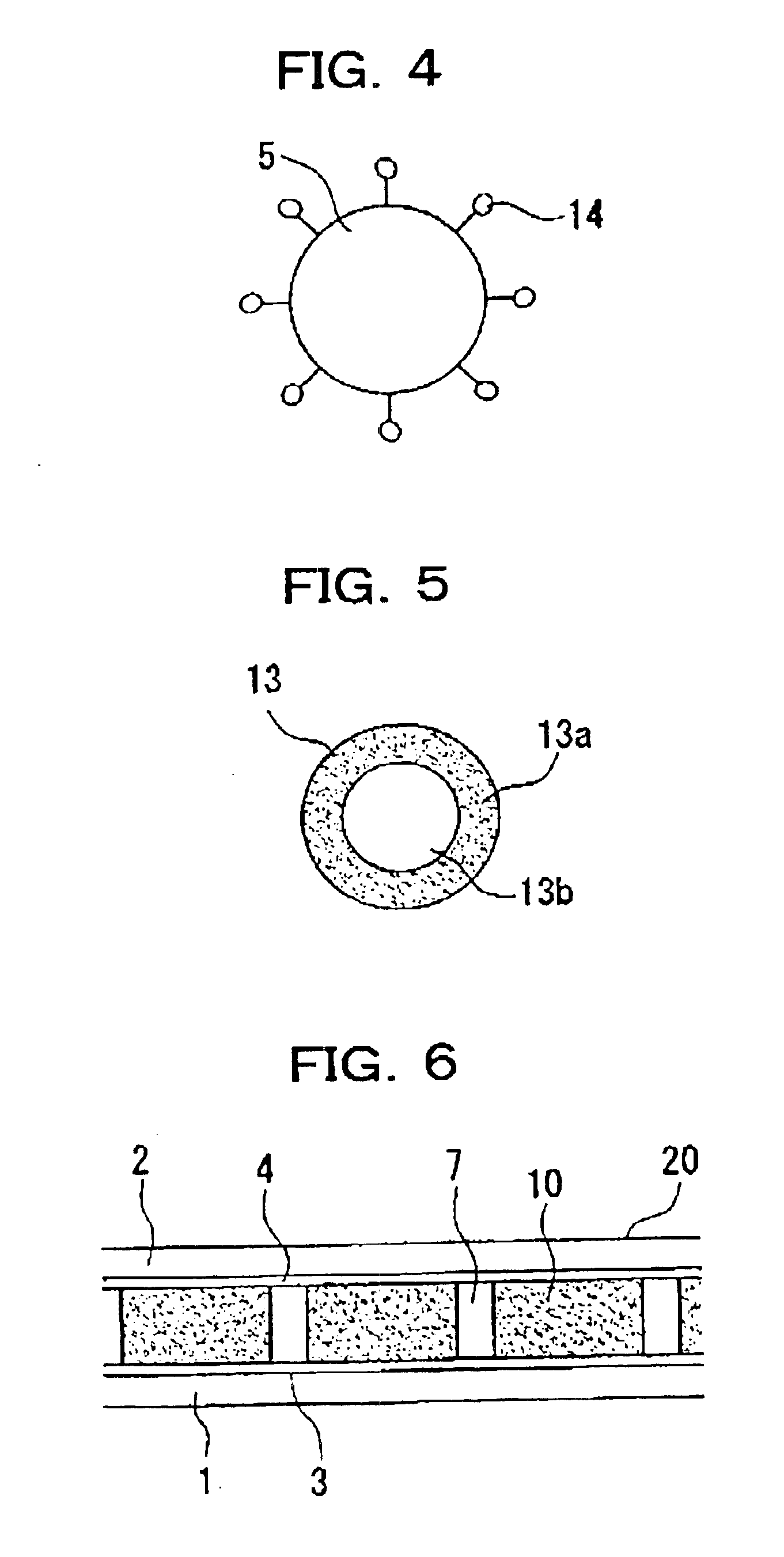
An electrophoretic device 20 according to the present invention is shown in FIG. 6. The electrophoretic device 20 includes first and second substrates 1 and 2, spacers 7, a transparent electrode 4, an electrode 3, and an electrophoretic dispersion 10. The spacers 7 are disposed between the first and second substrates 1 and 2 so as to provide a predetermined distance therebetween. The second substrate 2 comprises, for example, a transparent material such as transparent glass or a transparent film. The transparent electrode 4 is disposed under the lower surface of the second substrate 2, the lower surface facing the first substrate 1. The transparent electrode 4 comprises, for example, indium tin oxide (ITO).

The first substrate 1 may not be transparent and may comprise, for example, glass or a film. The electrode 3 is disposed on the upper surface of the first substrate 1, the upper surface facing the second substrate 2. The electrode 3 may not be transparent and may comprise, for exa...

second embodiment

An electrophoretic device 20 according to the present invention is shown in FIG. 7. The electrophoretic device 20 of this embodiment includes first and second substrates 1 and 2, and microcapsules 40, disposed therebetween, containing the electrophoretic dispersion 10.

The microcapsules 40 may comprise gelatin, a urethane resin, a urea resin, or the like. The microcapsules 40 may be prepared by a known method such as an interfacial polymerization method, an in-situ polymerization method, a phase separation method, or a spray drying method. The microcapsules 40 preferably have even size in order to have superior display functions. The microcapsules 40 having even size can be obtained by a filtration method or a gravity separation method. The microcapsules 40 usually have a diameter of about 30 to 100 mm.

A microcapsule layer is disposed between the first and second substrates 1 and 2. The microcapsule layer may be formed according to the following procedure: the microcapsules 40 and a ...


PUM

PropertyMeasurementUnit
lengthaaaaaaaaaa
diameteraaaaaaaaaa
dielectric constantaaaaaaaaaa

Abstract

The invention provide an electrophoretic dispersion, used for electrophoretic devices, containing electrophoretic particles having a density precisely adjusted by a simple method in order to prevent the settlement of the electrophoretic particles. An electrophoretic dispersion can include a liquid dispersion media and electrophoretic particles, dispersed in the liquid dispersion media, including at least a coloring portion, a resin portion, and a plurality of hollow microcapsules. The electrophoretic particles can further include charge control portions according to needs.

Description

BACKGROUND OF THE INVENTION1. Field of InventionThe present invention relates to an electrophoretic dispersion and electrophoretic devices including the same. The present invention particularly relates to an electrophoretic dispersion containing a liquid dispersion medium and electrophoretic particles, dispersed in the medium, including at least coloring means and a resin portion and relates to an electrophoretic device including a pair of electrodes and the electrophoretic dispersion disposed between the electrodes.2. Description of Related ArtConventionally, electrophoretic display systems including electrophoretic devices are known. The electrophoretic devices each include a pair of electrodes and an electrophoretic dispersion disposed between the electrodes, wherein the electrophoretic dispersion contains a liquid dispersion medium and electrophoretic particles. In such electrophoretic devices, the distribution of the electrophoretic particles is changed when a voltage is applie...

Claims


Application Information

Patent Timeline
Patent Type & Authority Patents(United States)
IPC IPC(8): G02F1/01G02F1/167G02F1/16757
CPCG02F1/167G02F1/16757
Inventor KAWAI, HIDEYUKI
Owner SEIKO EPSON CORP
Learn More