
Data processing system and associated control chip and printed circuit board

a data processing system and control chip technology, applied in the direction of electrical programme control, program control, instruments, etc., can solve the problems of serious affecting the operation of the entire system, deteriorating signal quality, and increasing the probability of electrical signal corruption along the transmission route, so as to reduce the production cost of the printed circuit board

Inactive Publication Date: 2005-01-11
VIA TECH INC
View PDF2 Cites 18 Cited by
  • Summary
  • Abstract
  • Description
  • Claims
  • Application Information

AI Technical Summary

Benefits of technology

Accordingly, one object of the present invention is to provide a data processing system linking up a central processing unit, a control chip and a four-layered printed circuit board such that signal transmission is stabilized and production cost of the printed circuit board is reduced.
In brief, a printed circuit board having a stack of four layers is used in this invention to reduce production cost. Additionally, the wiring layout serving as a transmission path for critical signals only uses the first signal layers of the aforementioned substrate stacks concerned with the central processing unit and the control chip, and in accompanied with the first signal layer of the printed circuit board. Hence, the critical signals will be transferred under best transmission qualities due to the affections by charge flows from the power source layer are eliminated.

Problems solved by technology

Although the aforementioned wiring layout dispenses with the need to route electrical signals within a particular signal layer to a specific signal layer, such a design often lead to an increase in the probability of corruption of the electrical signal along the transmission route.
Hence, any minor deterioration of signal quality may seriously affect the operation of the entire system.
Hence, the actual cost of producing of a printed circuit board is much higher than the one illustrated.

Method used


Image

  • Data processing system and associated control chip and printed circuit board
  • Data processing system and associated control chip and printed circuit board
  • Data processing system and associated control chip and printed circuit board

Examples


Embodiment Construction

Reference will now be made in detail to the present preferred embodiments of the invention, examples of which are illustrated in the accompanying drawings. Wherever possible, the same reference numbers are used in the drawings and the description to refer to the same or like parts.

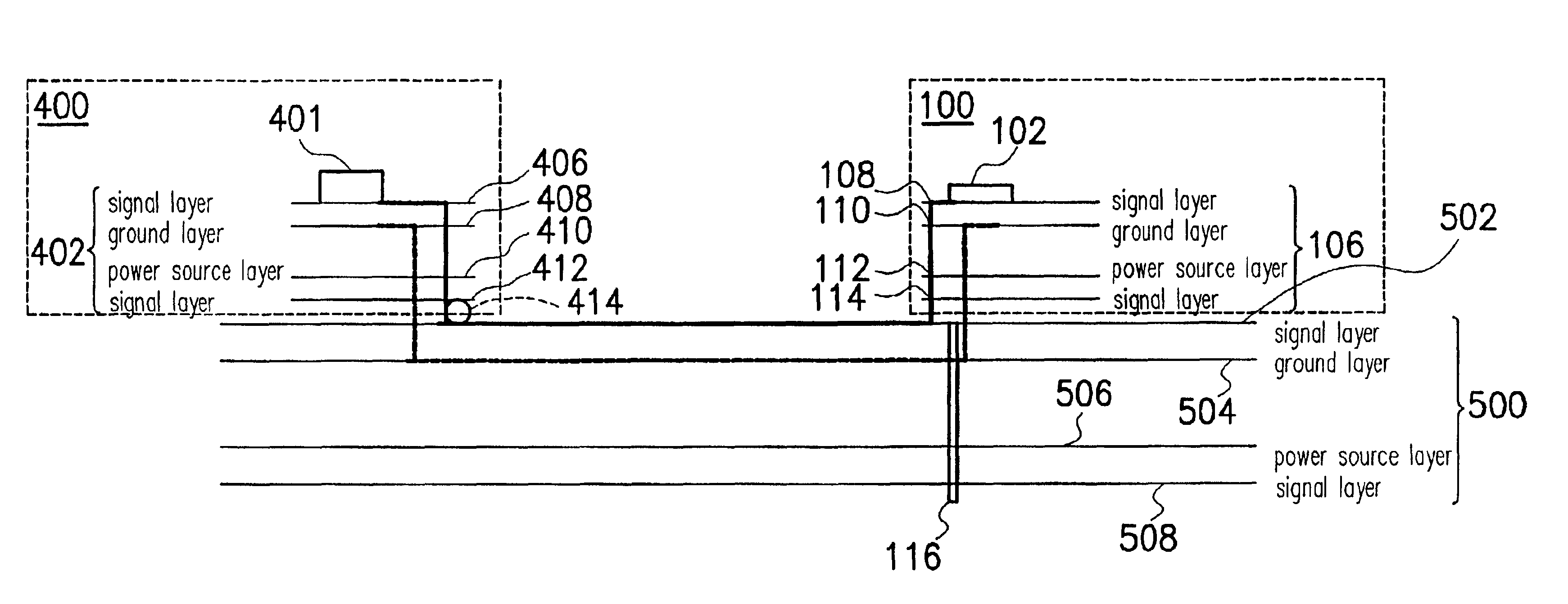
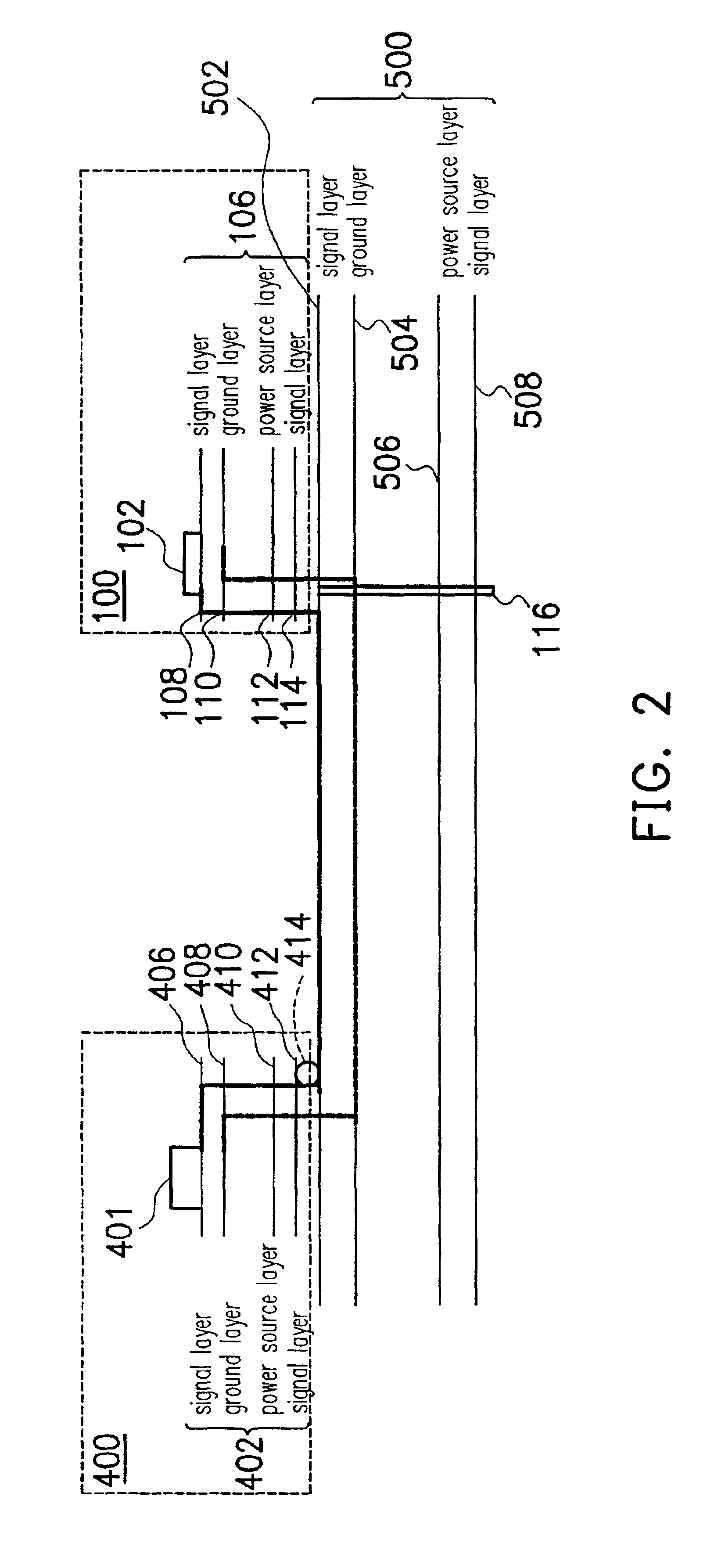
FIG. 2 is a schematic diagram showing a signal transmission wiring system between a central processing unit, a north bridge and a printed circuit board according to one preferred embodiment of this invention. The system includes a printed circuit board (PCB) 500, a central processing unit (CPU) 100 and a control chip 400. The printed circuit board 500 or the motherboard supports the central processing unit 100 such as an Intel Pentium IV. The central processing unit 100 has a plurality of contacts that connect a chip 102 to a substrate 106. The entire central processing unit 100 uses a plurality of through holes (or, vias) 116 that pass through the printed circuit board 500 for electrical connection. The c...


PUM


Abstract

A data processing system including a control chip, a central processing unit and a printed circuit board is provided. In the data processing system, the printed circuit board not only supports the control chip and the central processing unit, but also serves as an interface for transferring signals between the control chip and the central processing unit. Critical signals can be transmitted from the central processing unit to the control chip via the printed circuit with a better return path.

Description

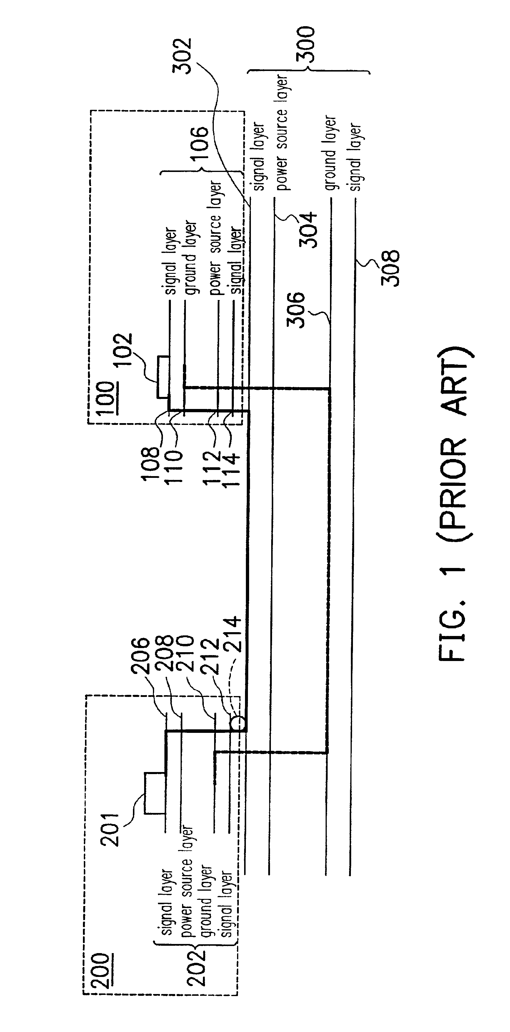
BACKGROUND OF THE INVENTION1. Field of InventionThe present invention relates to a data processing system and operating method. More particularly, the present invention relates to a data processing system and operating method that facilitates the maintenance of a set of uniform reference layers among a central processing unit, a control chip and a printed circuit board.2. Description of Related ArtFIG. 1 is a schematic diagram showing a conventional signal transmission wiring system between a central processing unit 100, a north bridge 200 and a printed circuit board (PCB) 300. As shown in FIG. 1, the central processing unit 100 includes a chip 102 and a substrate having a stack structure 106. The stack structure 106 within the central processing unit 100 includes, from top to bottom, a signal layer 108, a ground layer 110, a power source layer 112 and a signal layer 114. The north bridge 200 or the printed circuit board 300 respectively has its own substrate that further including ...

Claims


Application Information

Patent Timeline
Patent Type & Authority Patents(United States)
IPC IPC(8): H01L23/50H01L23/538H01L23/48H01L23/52H05K1/02H05K1/18H01L23/28H01L23/31H01L23/498H05K1/14
CPCH01L23/3128H01L23/49838H01L23/50H01L23/5383H01L24/49H05K1/0216H01L2924/10253H01L2224/48233H01L2924/014H01L2924/01079H01L2924/01033H01L24/48H05K2203/049H05K2201/10689H05K2201/10522H01L2223/6611H01L2224/48091H01L2224/48227H01L2224/48237H01L2224/49111H01L2924/01014H01L2924/01082H01L2924/14H01L2924/30107H05K1/181H05K2201/0792H05K2201/094H01L2924/00014H01L2924/00H01L2224/451H01L24/45H01L2224/45099H01L2224/05599
Inventor CHANG, NAI-SHUNG
Owner VIA TECH INC
Learn More