
Contact smart cards having a document core, contactless smart cards including multi-layered structure, pet-based identification document, and methods of making same

a contact smart card and document core technology, applied in the field of identification documents and smart cards, can solve the problems of not having an exhaustive list of possible smart card functionality, affecting the accuracy of identification, and the inability to verify one's true identity, so as to reduce the chances of loss, misappropriation or theft, and the effect of ensuring the validity

Inactive Publication Date: 2005-01-18
L 1 SECURE CREDENTIALING
View PDF30 Cites 128 Cited by
  • Summary
  • Abstract
  • Description
  • Claims
  • Application Information

AI Technical Summary

Benefits of technology

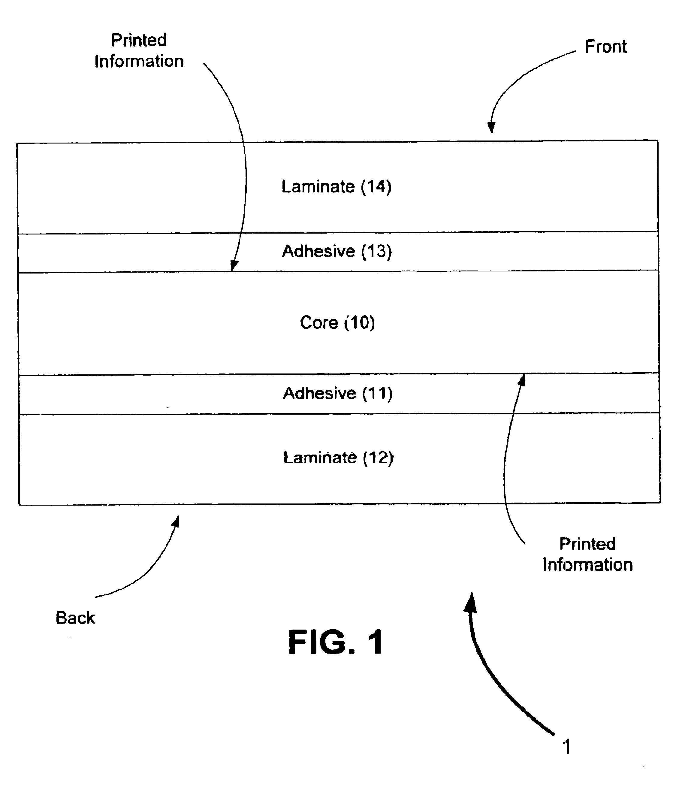
"The patent text discusses the limitations of conventional smart cards and proposes a solution. The solution involves a contact smart card with a flexible core layer made of synthetic paper. This helps reduce cracking and wear and tear. The card can also be printed on both sides with high-quality images and text. The print is covered with a laminate for protection. The patent also describes a process for controlling the issue of ID documents, which can be central or over-the-counter. The invention offers a way to improve the security of ID documents and prevent them from being easily copied or counterfeited."

Problems solved by technology

Verifying one's true identify is an ever-increasing problem.
Computer networks and secure areas have been breached with misappropriated keys, passwords and codes.
Of course, this is not an exhaustive list of possible smart card functionality.
In fact, printing is not always possible on both sides of the card—due to the contact area presented by a smart card module.
Even if a smart card is printed after embedding an integrated circuit module, the printing may nevertheless be vulnerable to malicious attacks (e.g., by changing information printed on the smart card).
We have found additional limitations that are associated with conventional smart cards.
In the case of contact smart cards, some of these problems include the smart card module popping off the card when flexed, flex stresses that damage the smart card module, and / or the card itself cracking with normal wear and tear.

Method used


Image

  • Contact smart cards having a document core, contactless smart cards including multi-layered structure, pet-based identification document, and methods of making same
  • Contact smart cards having a document core, contactless smart cards including multi-layered structure, pet-based identification document, and methods of making same
  • Contact smart cards having a document core, contactless smart cards including multi-layered structure, pet-based identification document, and methods of making same

Examples


example)

Milling Tool (Example)

FIGS. 5A-5D are diagrams of a milling tool that can be used to mill a cavity in an ID document. It should be appreciated that this is but one of many tools that can be used to provide a cavity in an identification document. In some cases, a laser or chemical process is used to create a cavity. In other implementations, conventional tools or cutters are used to machine or cut a cavity in an identification document. It will also be appreciated that while specific dimensions (in millimeters) are provided in the FIG. 5 representations, the present invention is not so limited. Indeed the dimensions can be changed in many respects without deviating from the scope of this aspect of the present invention.

With reference to FIGS. 5A and 5B, the cutting tool 50 preferably includes a shaft 51 having a first 52 and second 54 section. The shaft 51 can be fluted as shown in the figures. The first section 52 includes a first cutting edge 52a and the second section 54 includes ...


PUM

PropertyMeasurementUnit
angleaaaaaaaaaa
thicknessaaaaaaaaaa
thicknessaaaaaaaaaa

Abstract

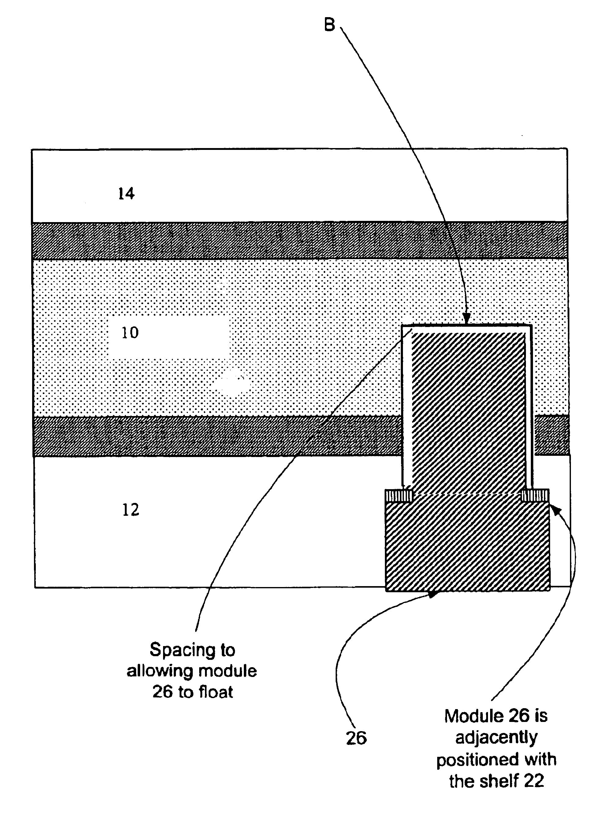
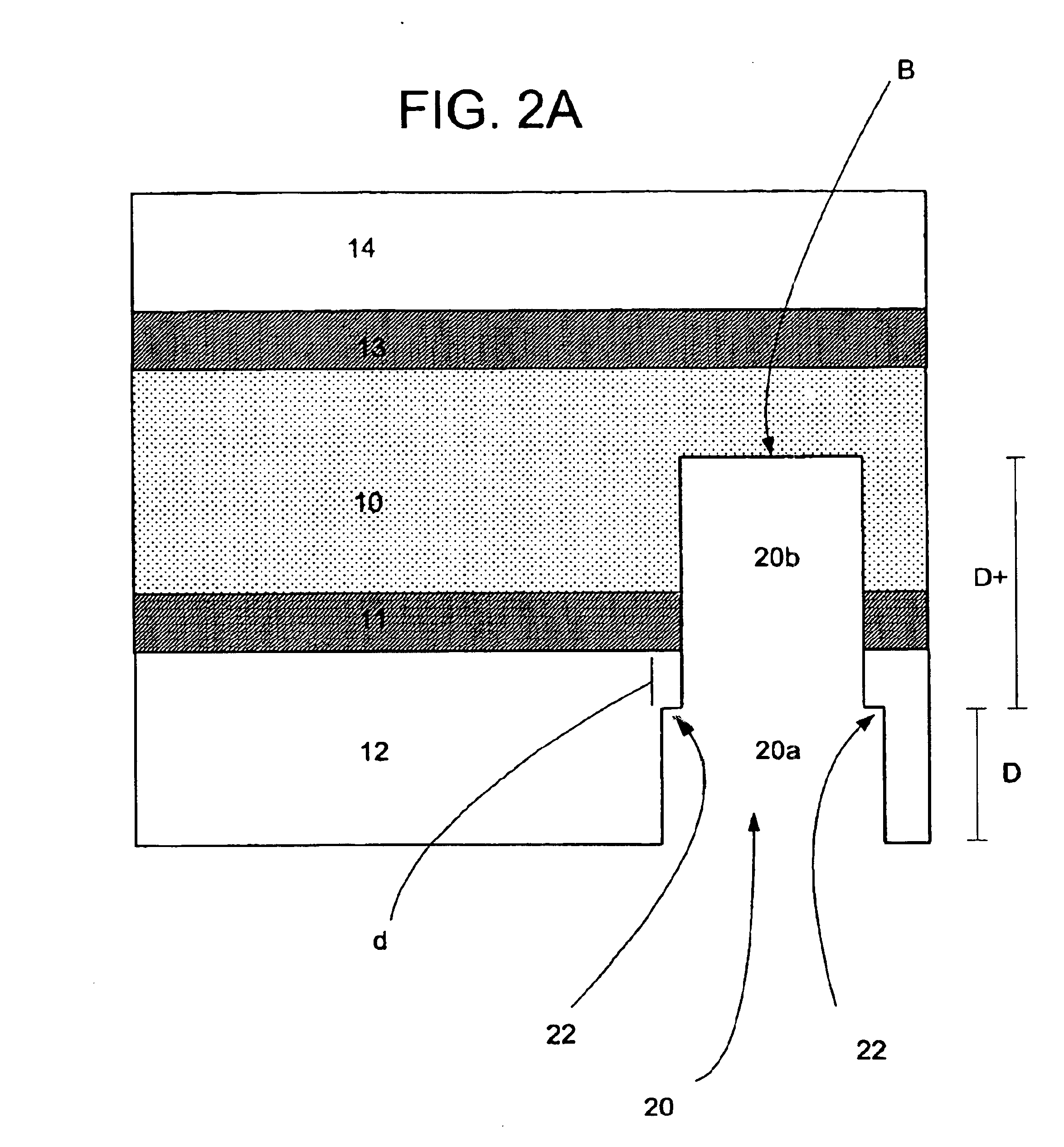
The present invention relates to identification documents and smart cards. In one implementation, we provide a smart identification document including a document core. The document core is printed and laminated. The laminated core is milled to create a cavity. An integrated circuitry module is provided in the cavity. In one implementation, the cavity includes an upper cavity and a lower cavity. A laminate layer houses the upper cavity while the lower cavity extends into the document core. The upper cavity's aperture exceeds the aperture of the lower cavity resulting in a ledge in the laminate layer. A portion of the module may rest on the ledge, while another portion of the module may extend into the lower cavity. In another implementation, we provide a contactless smart card including a multi-layered structure. The structure includes a carrier layer including the smart card electronics. The carrier can be permeable (like a mesh or scrim) so that additional layers may be laminated into or through the carrier layer. A multi-layer structure provides a enhanced durability and helps protect the smart card electronics. In still another implementation, we provide a PET-based identification document. The PET-based document includes favorable durability and earth-friendly characteristics.

Description

TECHNICAL FIELDThe present invention relates generally to identification documents and smart cards.BACKGROUND AND SUMMARYVerifying one's true identify is an ever-increasing problem. Identify theft is rampant, and stolen identifies have even been used to facilitate terrorist attacks. Computer networks and secure areas have been breached with misappropriated keys, passwords and codes. Conventional solutions typically include a photo identification document having a photographic quality image of the license holder on the document protected from tampering by one or more security feature. Another solution is the use of so-called “smart cards.”The term “smart card” as used herein is defined broadly to generally include a device that carries information. (The definition of a smart card used in this application is broad enough to include so-called radio frequency identification cards—or RFID cards.). Typically, a smart card includes a microprocessor (or electronic processing circuitry) and / ...

Claims


Application Information

Patent Timeline
Patent Type & Authority Patents(United States)
IPC IPC(8): G06K19/06B23C5/10G06K19/077
CPCB23C5/10G06K19/077G06K19/07722G06K19/07728G06K19/07745G06K19/07749Y10T409/303752B32B2305/342B32B2367/00B32B2425/00B32B2519/02H01L2924/0002B23C2210/0442Y10T407/19H01L2924/00
Inventor JONES, ROBERTANDERSON, JOSEPHBI, DAOSHENREGAN, THOMASMAILLOUX, DENNIS
Owner L 1 SECURE CREDENTIALING
Learn More