Blood pressure monitoring device and method of manufacturing a parts mounting module of a blood pressure monitoring device

a technology of blood pressure monitoring and parts mounting, which is applied in the direction of angiography, catheters, diagnostic recording/measuring, etc., can solve the problems of imposing limitations on the freedom of design and relative arrangement of individual components, and affecting the accuracy of blood pressure monitoring devices. , to achieve the effect of high assembly efficiency, reduced manufacturing cost and high overall dimension

Inactive Publication Date: 2005-01-18
KAZ USA
View PDF6 Cites 1 Cited by
  • Summary
  • Abstract
  • Description
  • Claims
  • Application Information

AI Technical Summary

Benefits of technology

This simplifies manufacture in so far as it obviates the step of adhesive-bonding a film to the upper side of the parts mounting module. The arrangement of the fluid channel completely in the interior of the module material increases the resistance of the fluid channel walls to pressure. The known pressure pulse characteristic is thus prevented from developing, and the accuracy of measurement is enhanced. Furthermore, the routing of the fluid channel can be designed without having to make allowance for the film to be adhered. There is no need for the fluid channel to extend along an upper side which has to be plane or allows only a one-dimensional curvature to ensure adhesion of the film. Rather, the fluid channel may be routed freely, resulting in a great freedom of design with respect to the arrangement of the components of the fluid pressure system. This enables the blood pressure monitoring device to be built to compact dimensions.
In particular, the fluid channel may be routed in a three-dimensional curvature extending in several planes. This results in maximum design freedom as regards the arrangement of the components of the blood pressure monitoring device.
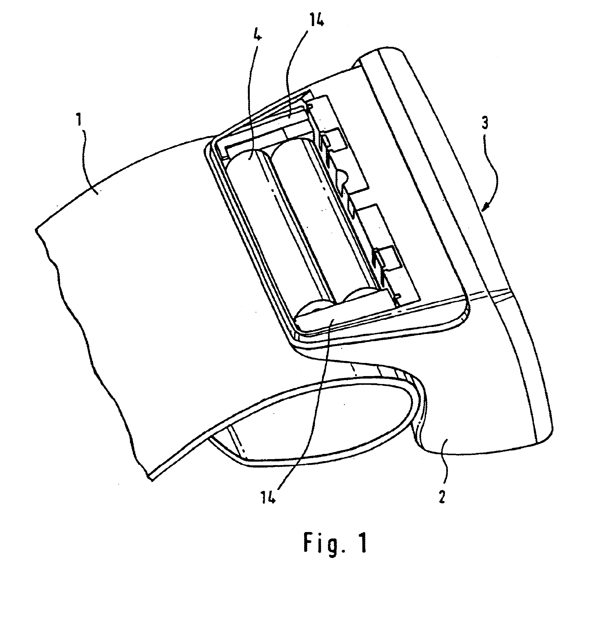
According to another aspect of the present invention, all the remaining components (including, for example, deflation valve, pump, pressure sensor, inclination sensor, electronic components, printed circuit board, power source and cuff) of the blood pressure monitoring device are mounted on the mounting module. Hence the parts mounting module is the central part on which the other components are mountable directly. Particularly the cuff of the blood pressure monitoring device may be snapped onto the mounting module directly, thereby eliminating the need to provide tubing for inflating the cuff and enabling the blood pressure monitoring device to be built to highly compact overall dimensions. It is also possible to mount on the central parts mounting module a control unit for evaluation of the measurement values and determination of the blood pressure and the contacts of a power source for operating the evaluating or control unit. Mounting all the components of the blood pressure monitoring device on the mounting module has the advantage that the blood pressure monitoring device builds to compact dimensions, irrespective of the previously described special configuration of the fluid channel or its wall.
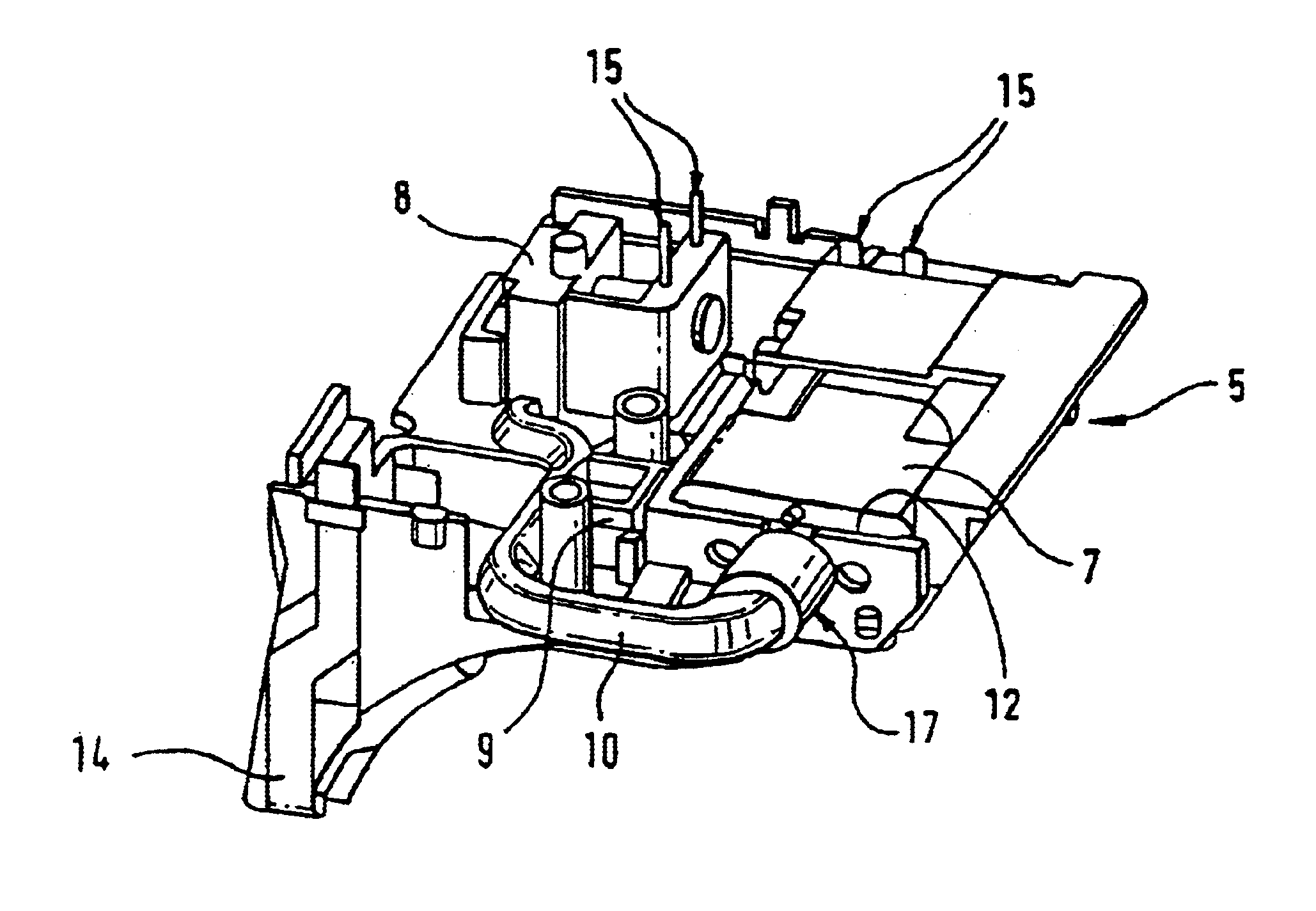
Plural advantages are attendant upon the fact that the components of the blood pressure monitoring device such as the pump, the printed circuit board, the cuff, the pressure valve, the pressure sensor, the deflation valve where applicable, the power source, etc. are not received in recesses specifically formed in the housing for this purpose, provision being made instead for a parts mounting module formed (and manufactured) separate from the housing, which receives all the components. For one purpose, this modular design allows great freedom regarding the shape design of the housing because otherwise the component geometry would dictate the shape design of the housing to a certain extent. For another purpose, the arrangement of the components of the blood pressure monitoring device in bays in the mounting module or a chassis part ensures great ease of assembly of the blood pressure monitoring device. The quality assurance test of all the functional parts is performed on the fully packed mounting module without the housing, which eliminates the need to protect a housing from being marred during the test cycle, in addition to providing for ready accessibility of all the components. Furthermore, this modular design employing a parts mounting module or chassis in which all the components are received is also highly impact resistant.
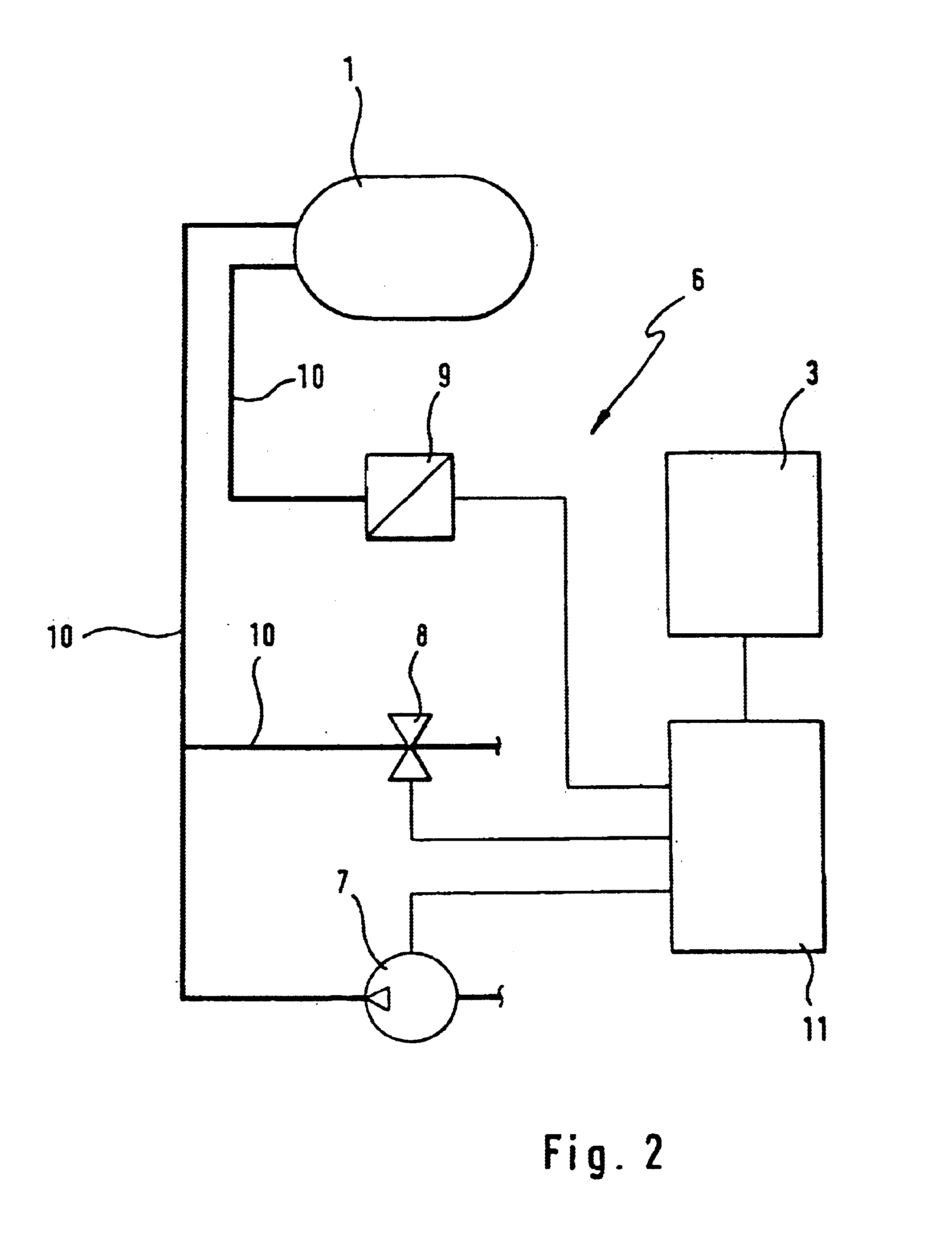
To obtain a particularly compact blood pressure monitoring device the components of the fluid pressure system having an electrical connection, in particular the pump, the pressure valve and the pressure sensor, are advantageously arranged such that their electrical connections lie essentially in one plane. The electrical components may be connected to a printed circuit board directly and, via this board, to a corresponding control unit. It is thus possible for the electric control and supply to be free from wiring. This facilitates the assembly significantly. The components of the blood pressure monitoring device equipped with electrical connections are all arranged on the one side of the mounting module, so that the contacts are located approximately in one plane, permitting direct connection or soldering to the printed circuit board. Mounted on the printed circuit board are also all the typical electrical components including, for example, resistors, capacitors, ASICs, MPU or control unit and programmable controller, in order to control all the components of the blood pressure monitoring device in accordance with the oscillometric method.
According to an advantageous embodiment of the invention, a bifurcating fluid channel may be provided in the parts mounting module. Preferably, a first step includes forming the fluid channel along the one branch, and a second step includes forming the other branch. Conveniently, the first step further includes opening the outlet of the fluid channel of the one branch while closing the outlet of the fluid channel of the other branch and introducing the pressure fluid into the fluid channel from the upstream side of the bifurcation. The second step further includes closing the outlet of the fluid channel of the one branch while opening the outlet of the fluid channel of the other branch, so that the fluid channel can be blown out along the other branch.

Problems solved by technology

An automated assembly of this “internal tubing” is practically not possible because of the soft material properties and the small dimensions of the tubes.
For the film to adhere it is however necessary for the upper side to be plane or to have no more than a one-dimensional curvature, which imposes limitations on the freedom of design and relative arrangement of the individual components.
In addition, the film is relatively sensitive and hence subject to increased wear.
Furthermore, the film is extensible to a considerable degree which may result in a pressure pulse characteristic developing in the fluid channel which produces a measurement error.
Finally, contact with the cover film entails the risk of pressure surges occurring in the fluid channel, hence introducing measurement errors.

Method used


Image

  • Blood pressure monitoring device and method of manufacturing a parts mounting module of a blood pressure monitoring device
  • Blood pressure monitoring device and method of manufacturing a parts mounting module of a blood pressure monitoring device
  • Blood pressure monitoring device and method of manufacturing a parts mounting module of a blood pressure monitoring device

Examples


Embodiment Construction

FIG. 1 shows a blood pressure monitoring device comprising a cuff 1 inflatable with air. The cuff 1 can be wrapped around a subject's arm or wrist for occluding a blood vessel by inflation—as is conventional practice in the oscillometric method of measuring blood pressure. As shown in FIG. 1, the blood pressure monitoring device further comprises a housing 2 which on its side adjoining the cuff is shaped to conform to the arm contour. Arranged on the side facing away from the cuff is a display device 3 for indicating the measured blood pressure (systolic, diastolic and pulse). The housing 2 has a cover shown removed in FIG. 1 to insert batteries 4 for power supply of the blood pressure monitoring device. In the interior of the housing 2 is a central parts mounting module 5 which will be described in greater detail subsequently.

The blood pressure monitoring device is equipped with a fluid pressure system 6 for inflating the cuff 1. As FIG. 2 shows, the fluid pressure system 6 compris...


PUM

PropertyMeasurementUnit
pressureaaaaaaaaaa
pressureaaaaaaaaaa
pressureaaaaaaaaaa

Abstract

The invention is directed to a blood pressure monitoring device comprising a central parts mounting module and to a method of manufacturing this parts mounting module. According to the invention fluid channels are produced by gas injection into the interior of the parts mounting module, the walls bounding the fluid channels being completely formed by the material of the parts mounting module. The injection of gas continues for as long as a core of the parts mounting module is still in the liquid phase in the area of the fluid channel, whilst an outer area surrounding the core has already solidified, so that the pressure fluid expels the liquid core area, producing a tubular fluid channel.

Description

FIELD OF THE INVENTIONThis invention relates to a blood pressure monitoring device with a fluid pressure system for filling a cuff with fluid under pressure and with a parts mounting module having bays for receiving components of the fluid pressure system, provision being made for at least one fluid channel integrated in the mounting module and serving the function of connecting the components.The present invention further relates to a method of manufacturing such a parts mounting module with a fluid channel extending in the interior thereof. Furthermore, the invention relates to a die for implementing the method.BACKGROUND OF THE INVENTIONIt is conventional practice to apply the cuff of a blood pressure monitoring device to a subject's limb, in particular to his or her upper arm or wrist, and inflate it until arterial occlusion sets in. The fluid pressure system provided for this purpose typically comprises a pump for cuff inflation, a valve for discharge of the pressure fluid, and...

Claims


Application Information

Patent Timeline
Patent Type & Authority Patents(United States)
IPC IPC(8): A61B5/022A61B5/0235B29C45/00B29L31/60
CPCA61B5/0235A61B5/022
Inventor FREUND, DIRKGIERSIEPEN, MARTINHARTTMANN, BRIGITTEHECK, ULRICHHOLLINGER, STEFANKRESSMANN, FRANKRONNEBERG, GERRITSCHNAK, FREDRENNEFELD, CHRISTOPHHANS, RAINER
Owner KAZ USA
Why Eureka
Try Eureka