
Alumina insulation for coating implantable components and other microminiature devices

a micro-miniature device and alumina insulation technology, applied in the direction of gas-filled discharge tubes, diaphragms, packaged goods, etc., can solve the problems of high leakage rate of alumina insulators, high cost, and high cost, and achieve excellent insulative properties, safe implanting in living tissue for long periods of time, and easy application

Inactive Publication Date: 2005-01-18
MEDTRONIC MIMIMED INC
View PDF3 Cites 216 Cited by
  • Summary
  • Abstract
  • Description
  • Claims
  • Application Information

AI Technical Summary

Benefits of technology

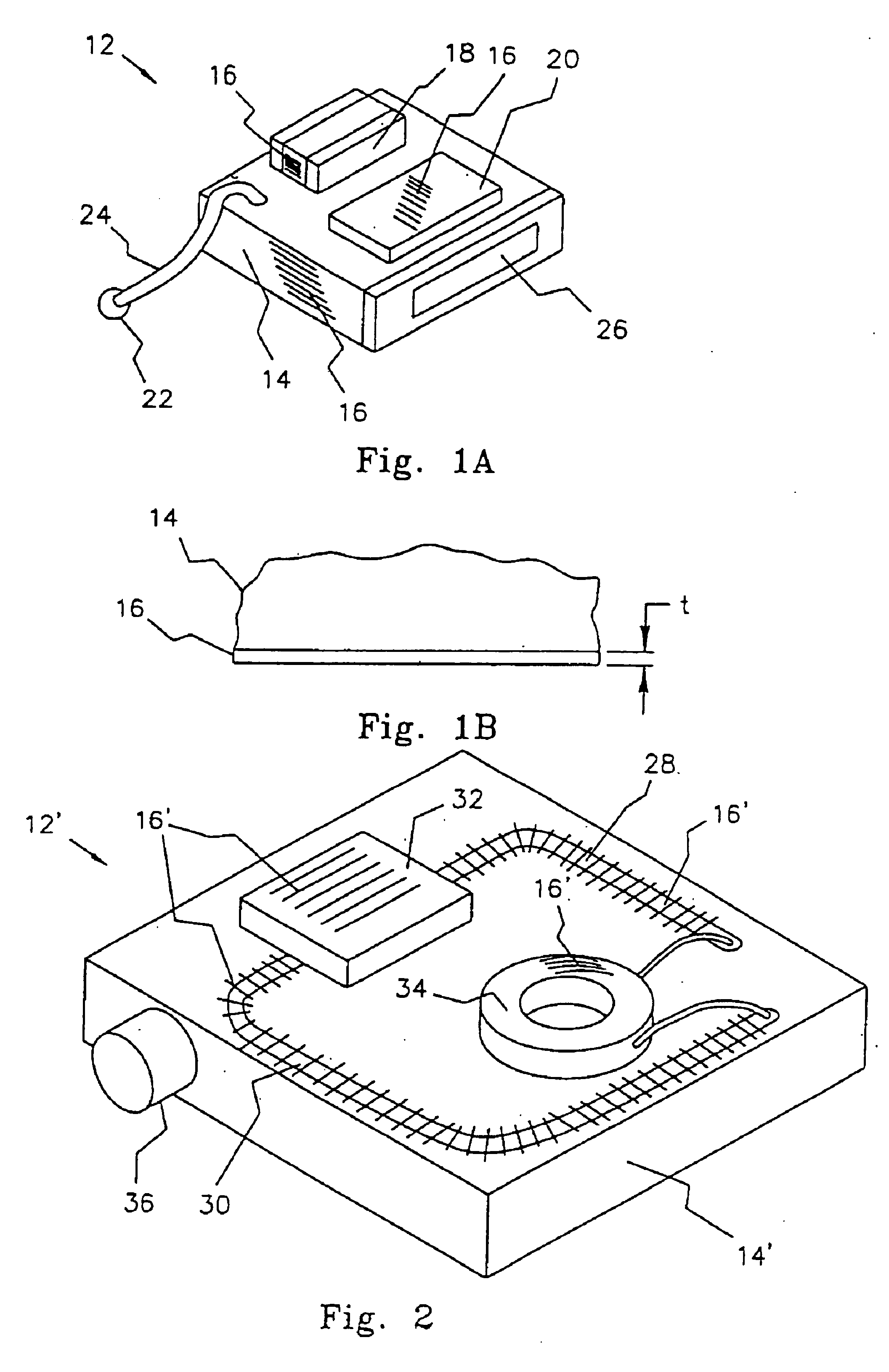
The present invention provides a protective, biocompatible coating or encapsulation material that may be applied to a component or device intended to be implanted in living tissue. The coating or encapsulation material comprises a thin layer or layers of alumina, zirconia, and / or alloys of alumina and / or zirconia. Advantageously, a thin alumina or zirconia layer applied in accordance with the present invention may be applied at relatively low temperature. Once applied, the coating provides excellent hermeticity, and prevents electrical leakage, while retaining a microminiature size. The layer of alumina or zirconia insulation can be made as thin as about {fraction (1 / 1000)} of an inch (Note: {fraction (1 / 1000)} inch=0.001 inch=1 mil=25.4 microns) or less while still retaining excellent insulating characteristics. For example, in accordance with one aspect of the present invention, an alumina coating having a thickness that is less than about 5-10 microns provides an insulative coating that exhibits less than about 12 nA of leakage current over an area 75 mils by 25 mils while soaking in a saline solution at temperatures up to 80° C. over a three month period.
It is an object of the invention to provide a biocompatible, thin, insulative coating that is easy to apply to a wide variety of different shapes and sizes of components and devices, and that once applied provides excellent insulative properties for the covered component or device over a long period of time, thereby allowing the covered component or device to be safely implanted in living tissue for long periods of time.
It is a further object of the invention, in accordance with one aspect thereof, to provide a biocompatible, insulative coating that may be applied to implantable components or devices of various shapes and sizes, and wherein the coating is: (1) less than about 10 microns thick; (2) submersible for long periods of time in water or saline solution or any other conductive fluids; (3) made from alumina, zirconia or alloys of alumina and / or zirconia, or other substances having properties the same as or similar to alumina, zirconia and / or alloys of alumina and / or zirconia; (4) amenable to being applied using a batch process, e.g., a process wherein 1000 or more devices or components may be coated at the same time using the same process, such as an evaporative coating, vapor deposition, or ion-beam deposition (IBD) process; and / or (5) extremely strong in the lateral direction.

Problems solved by technology

In these applications, however, the alumina insulator is very thick and is used only as part of the feedthrough for the implantable device and is often carried by a metal ferrule.
But all such materials, except as discussed herein, typically leak at a rate greater than about 1 μA / cm2.
A problem with the related art is that the thickness of the insulation needed for implantable devices is typically on the order of about several millimeters thick.
None of the related art, to applicant's knowledge, has heretofore achieved an insulating layer with very small dimensions and free of micro-holes.
The presence of a micro-hole, or “pin-hole”, destroys the insulating properties which may lead to eventual failure of the implantable device.
Further, some components or devices which need to be implanted in living tissue, such as magnets, are susceptible to extremely high temperatures, i.e., extremely high temperatures may damage or destroy such components.

Method used


Image

  • Alumina insulation for coating implantable components and other microminiature devices
  • Alumina insulation for coating implantable components and other microminiature devices
  • Alumina insulation for coating implantable components and other microminiature devices

Examples


example

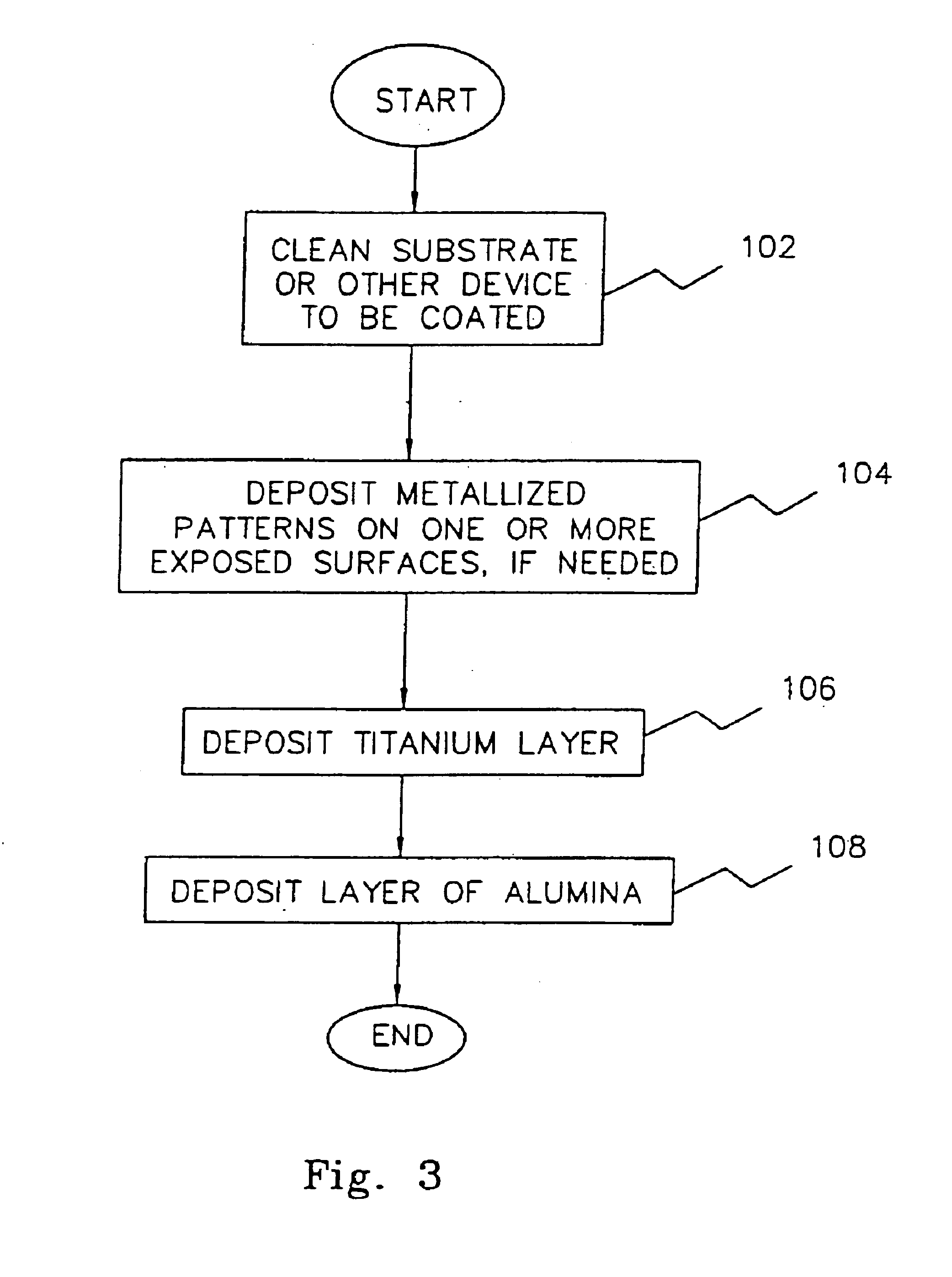
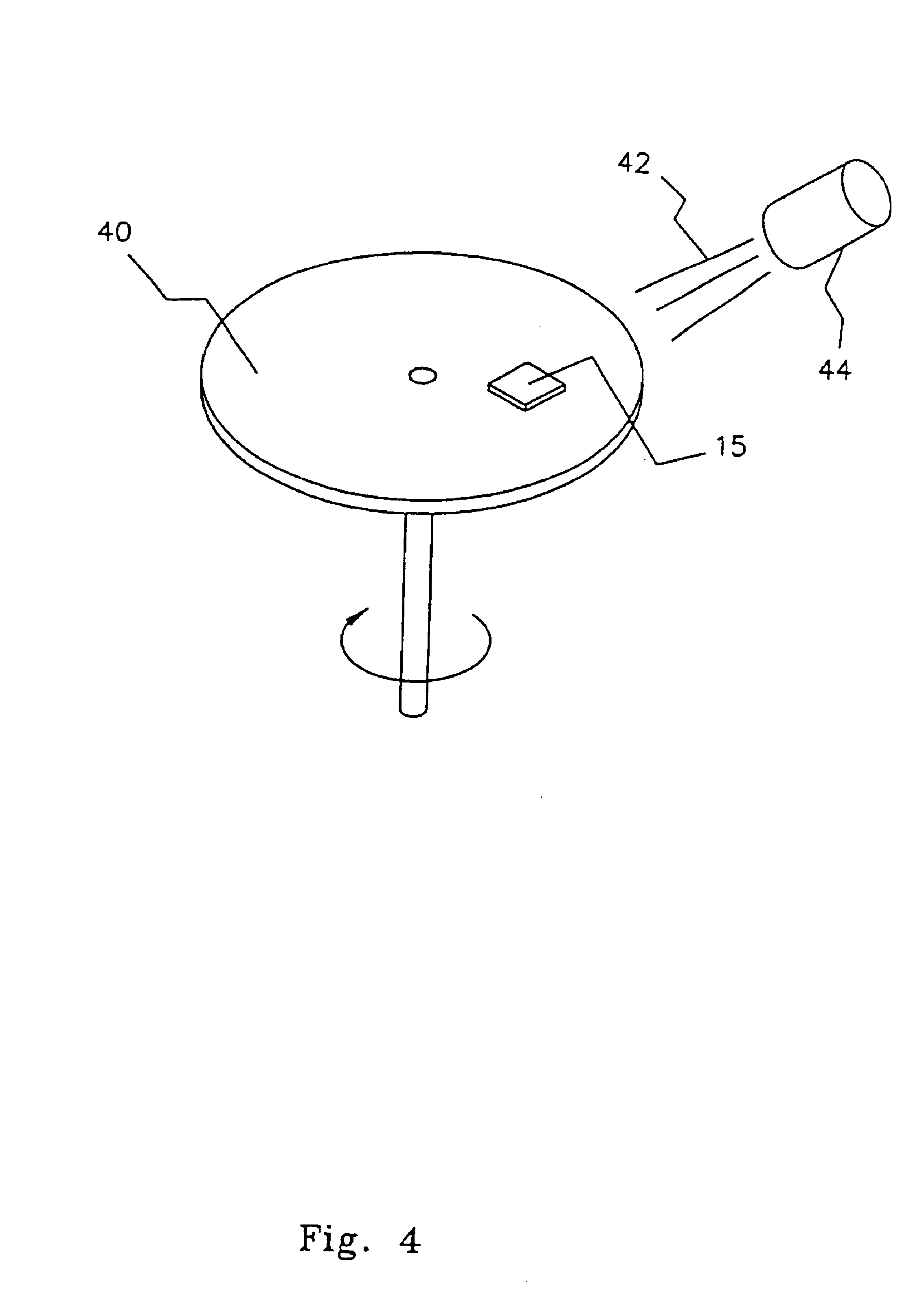
A test specimen that included a plurality of 75 mil by 25 mil and 75 mil by 5 mil metallized pads deposited on an alumina substrate was constructed using conventional techniques. The plurality of metallized pads are separated from one another by a distance of about 2.0-2.5 mils. A layer of alumina insulator approximately 5-6 microns thick was deposited on and between the metallized pads using an ion-enhanced evaporative sputtering technique. The ion-enhanced evaporative sputtering was performed in an evacuated chamber at a moderate temperature of about 60-100° C., and allowed to cure for approximately 0.5-4 hours. The test specimen was subsequently submersed in a saline solution at 87° C. for three months. Leakage current between the metallized pads and the saline solution was measured and did not exceed 10 pA across the 6 micron size insulating layer. In addition leakage current between each metallized pads did not exceed 10 pA across the 2.0-2.5 mil spacings.


PUM

PropertyMeasurementUnit
Temperatureaaaaaaaaaa
Timeaaaaaaaaaa
Thicknessaaaaaaaaaa

Abstract

A protective, biocompatible coating or encapsulation material protects and insulates a component or device intended to be implanted in living tissue. The coating or encapsulation material comprises a thin layer or layers of alumina, zirconia or other ceramic, less than 25 microns thick, e.g., 5-10 microns thick. The alumina layer(s) may be applied at relatively low temperature. Once applied, the layer provides excellent hermeticity, and prevents electrical leakage. Even though very thin, the alumina layer retains excellent insulating characteristics. In one embodiment, an alumina layer less than about 6 microns thick provides an insulative coating that exhibits less than 10 pA of leakage current over an area 75 mils by 25 mils area while soaking in a saline solution at temperatures up to 80° C. over a three month period.

Description

BACKGROUND OF THE INVENTIONThe present invention relates to very thin layers of electrical insulation that may be used to coat and protect microminiature components and devices that are intended to be implanted in living tissue and / or to maintain electrical leakage of such components / devices within acceptable limits, e.g., less than 1 μA / cm2 when the components and / or devices are submerged in water or salt water. More particularly, the invention relates to the use of alumina or aluminum oxide as a safe, biocompatible, coating material that provides a reliable, protective and insulative layer or coating for components, or devices comprised of components, wherein the insulating layers can be made extremely thin, on the order of microns, yet wherein the electrical leakage through the thin insulative layer (when the coated component or device is implanted or otherwise immersed in a saline solution or in distilled water) is less than about 1 μA / cm2 (or less than about 12.1 nA for an area...

Claims


Application Information

Patent Timeline
IPC IPC(8): G03F7/20H01L21/02H01L21/308G03F1/14A61L2/00A61N1/02B05D3/00B32B9/00C23C14/00C23C14/04G03F1/00H01L23/29H05K3/28
CPCC23C14/042G03F7/70641H01L21/308H01L23/291H05K3/284A61N1/02Y10T428/24802G03F1/144H01L2924/0002A61N1/375Y10T428/265Y10T428/24926Y10T428/24917Y10T29/49144H01L2924/00
Inventor SCHULMAN, JOSEPH H.LUCISANO, JOSEPH Y.SHAH, RAJIVBYERS, CHARLES L.PENDO, SHAUN M.
Owner MEDTRONIC MIMIMED INC
Learn More