
Gas-supplying apparatus for fuel cell

a fuel cell and gas supply technology, applied in the direction of machines/engines, electrochemical generators, positive displacement liquid engines, etc., can solve the problems of large amount of pressure loss, waste, and inability to generate power, and achieve the effect of easy discharge of produced water

Inactive Publication Date: 2005-01-18
HONDA MOTOR CO LTD
View PDF5 Cites 9 Cited by
  • Summary
  • Abstract
  • Description
  • Claims
  • Application Information

AI Technical Summary

Benefits of technology

In light of the situations of the prior art, an object of the present invention is, therefore, to provide a gas-supplying apparatus for a fuel cell, whose electric power consumption is small, and which can easily discharge the produced water, whereby the fuel cell can be operated under adequate conditions.
According to this configuration, the fuel cell is operates at a negative pressure not greater than atmospheric pressure. Consequently, the pressure loss can be decreased in comparison with the case where the supply air is compressively transferred as in the conventional apparatus. Also, the negative pressure accelerates the vaporization of the produced water. What is more, assuming that the flow amount or the supply gas is the same, the flow rate of the supply air in the case of the drawing of the supply air (negative pressure) as in the present invention is faster than that in the case of compressively transferring the supply air as in the prior art this makes it possible to accelerate the vaporization rate.
Also, according to the configuration of the present invention, the pressure control (negative pressure control) can be carried out by both of the gas-sucking means provided on the downstream of the fuel cell and the pressure controller provided on the upstream of the fuel cell. Consequently, in comparison with the negative pressure control only by the gas-sucking means, good controllability can be obtained with decreasing the motive power for heightening the negative pressure.
One of main reason why the cell voltage is decreased is that the produced water stays within the fuel cell. However, according to this configuration where the negative pressure is controlled to be large when the cell voltage is decreased, the produced water remaining within the fuel cell is drawn out by the negative pressure, making it possible to recover the cell voltage.

Problems solved by technology

While the fuel cell produces water due to an electrochemical reaction, the produced water, if it stays within the fuel cell, inhibits the power generation.
However, the gas-supplying apparatus for a fuel cell in which the supply air is compressively transferred has the disadvantage in terms of a large amount of pressure loss, which consumes wasteful electric power (parasitic power of the fuel cell) as a motive force of the air compressor.
On the other hand, when an airflow amount becomes large, pressure loss also becomes large accordingly.
For this reason, a large amount of the motive force (electric power) is required for discharging the produced water, which leads to the problem that the produced water can be discharged only with difficulty.

Method used


Image

  • Gas-supplying apparatus for fuel cell
  • Gas-supplying apparatus for fuel cell
  • Gas-supplying apparatus for fuel cell

Examples


Embodiment Construction

The gas-supplying apparatus for a fuel cell according to one embodiment of the present invention will now be described in detail by referring to the drawings.

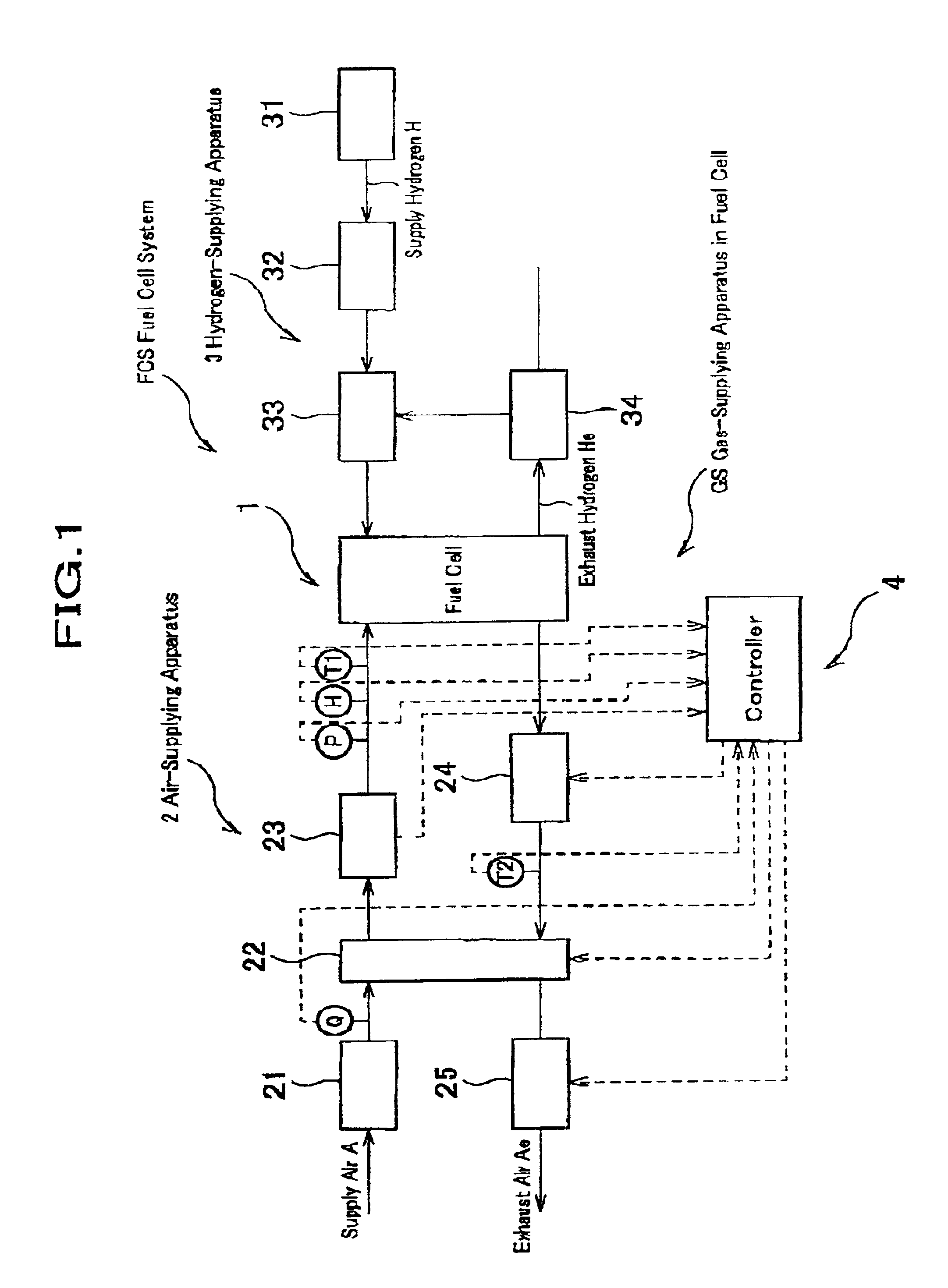
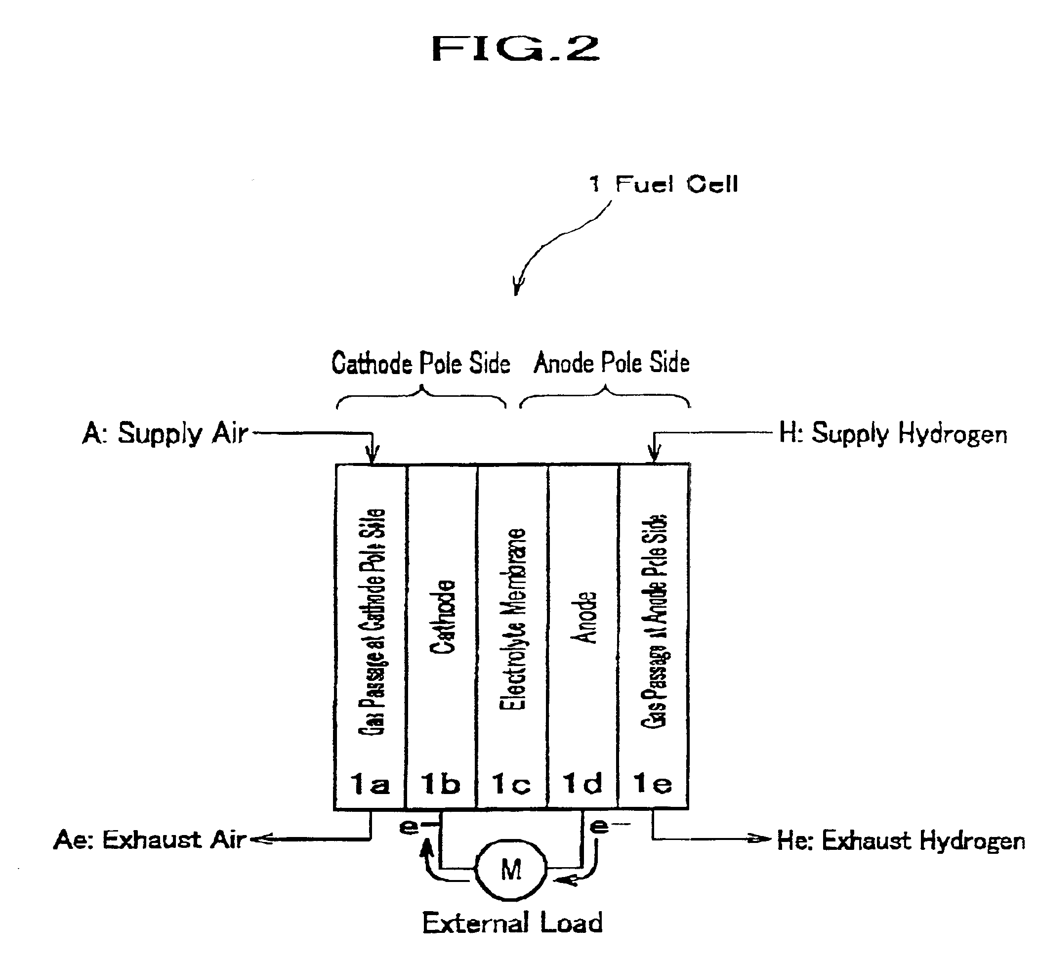
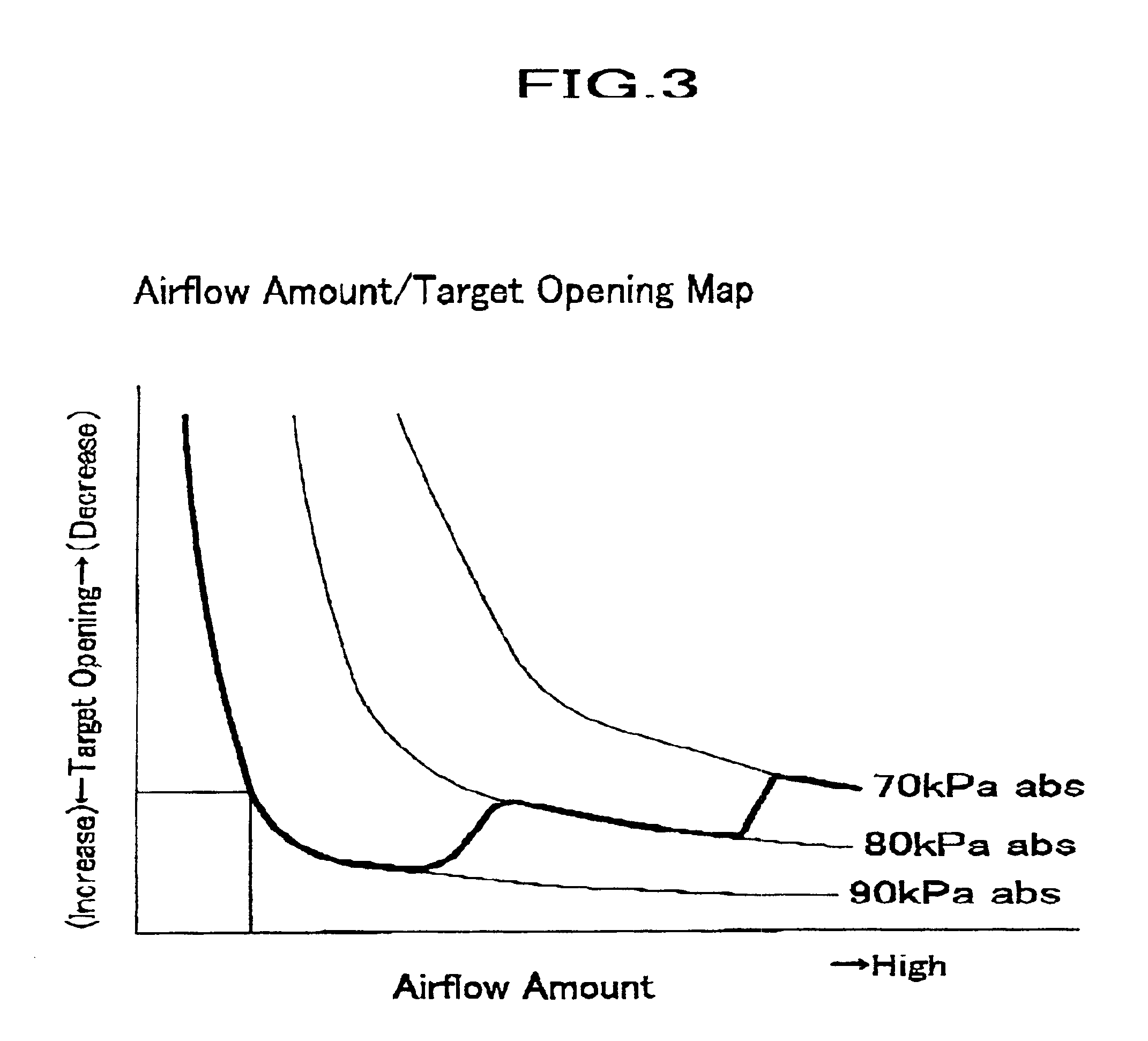
FIG. 1 is a drawing showing the whole of a fuel cell system including the gas-supplying apparatus according to one embodiment of the present invention. FIG. 2 is an explanatory view schematically showing the configuration of the fuel cell of FIG. 1. FIG. 3 is a map showing the relation between the airflow amount and the target opening utilizing one embodiment of the present invention.

A fuel cell system FCS shown in FIG. 1 is an electric power generation system based on a fuel cell 1. The fuel cell system FCS is mainly composed of the fuel cell 1, an air-supplying apparatus Z, a control unit 4, and the like. The fuel cell system FCS in this figure is intended to be carried on a fuel cell type electric powered vehicle.

As shown in FIG. 2, the fuel cell 1 is divided into a cathode side (an oxygen pole side) and an anode side (a hyd...


PUM


Abstract

A gas-supplying apparatus for a fuel cell, which generates electric power due to an electrochemical reaction between oxygen and hydrogen, during which water is produced, and which has respective gas passages within the duel cell according to the present invention comprises a gas-sucking means which supplies supply gas of the fuel cell provided on the downstream of the gas passage in a gas-flowing direction; and a pressure controller which controls the pressure of the supply gas within the fuel cell, provided on the upstream of the gas passage, whereby the water produced during the course of said electrochemical reaction is discharged. When the cell voltage is decreased, the apparatus of the present invention recovers the cell voltage by making the negative pressure large to accelerate the discharge of the produced water with minimized power consumption.

Description

BACKGROUND OF THE INVENTION1. Field of the InventionThe present invention relates to a gas-supplying apparatus for a fuel cell and a particularly to a gas-supplying apparatus for a fuel cell, which can decrease electric power consumption and which can make it easy to discharge the produced water to drive the fuel cell in an adequate manner.2. Description of Related ArtsA fuel cell (proton exchange membrane type fuel cell) has recently drawn considerable attention as a power source of an electric powered vehicle because of its cleanness and excellent energy efficiency. Into the fuel cell, fuel gas (hydrogen) and oxidant gas (air) are supplied to electrochemically generates power.As a gas-supplying apparatus for a fuel cell, which supplies gas to the fuel cell, an apparatus having an air compressor whose motive source is electric power generated by the fuel cell which is provided on the upstream of the fuel cell, and which compressively transfers supply air into the fuel cell has been...

Claims


Application Information

Patent Timeline
IPC IPC(8): E03B5/00F04B49/00H01M8/04H01M8/00H01M8/10
CPCH01M8/04089H01M8/04335H01M8/0435H01M8/04507H01M8/04559H01M8/04619H01M8/04753H01M8/04761H01M8/04828H01M8/04395H01M8/04141H01M8/04149H01M8/04179Y02E60/50Y10T137/86002
Inventor KOBAYASHI, TOMOKINUIYA, YOSHIO
Owner HONDA MOTOR CO LTD
Learn More