Lithium secondary cell and assembly thereof

a secondary cell and lithium technology, applied in the direction of cell components, sustainable manufacturing/processing, wound/folded electrode electrodes, etc., can solve the problems of poor assembly efficiency of a cell, inability to prevent cell explosion, and difficulty in mechanical production, so as to improve assembly efficiency and function. , the effect of improving productivity

Inactive Publication Date: 2005-01-18
NGK INSULATORS LTD
View PDF7 Cites 48 Cited by
  • Summary
  • Abstract
  • Description
  • Claims
  • Application Information

AI Technical Summary

Benefits of technology

The present invention has been completed to solve such conventional problems. Therefore, the present invention is aimed at providing a lithium secondary cell with an improved productivity by using an electrode cap improved in its assembly efficiency and its functionality.
In addition, the present invention further is aimed at providing an assembly of lithium battery cells which comprises a plurality of lithium secondary cells and a plurality of bus bars having an improved output performance by suppressing connection resistance at the time of connecting a plurality of cells in series so as to exert its performance sufficiently, and is aimed at improving productivity by simplifying the structure of the assembly of cells.
In this embodiment, it is preferable that at least one member of the plate member, the external terminal member, and the internal terminal member is produced by press processing or cold forging, and thereby reduction in process costs and improvement in the yield factor can be expected. At least two members of the plate member, the external terminal member and the internal terminal member are preferably produced by a method selected from a group consisting of friction bonding, brazing, welding, clamping and forging clamping, and any combination of those methods.

Problems solved by technology

However, the electrode cap described in JP-A-9-92335 is provided with a current lead-out function, a pressure release function and a function as an electrolyte solution injection port, but it is constructed by a number of parts, thus giving rise to a problem that assembly efficiency on a cell is bad and mechanical production is difficult.
In addition, this conventional electrode cap has, as shown in FIG. 17, a pressure release valve 49 disposed in the vicinity of the outer peripheral portion of the electrode cap remote from the central axis of the cell case 54 and thus is not good at releasing gas from the hollow portion of the winding core in which a lot of gas causing an increase of inner pressure is contained, giving rise to a problem that explosion of a cell cannot be prevented unless pressure release valves are disposed at both the electrode caps of the positive electrode and the negative electrode.
Moreover, the conventional electrode cap has, as shown in FIG. 17, electrolyte solution injection port 48 disposed in the vicinity of the outer peripheral portion of the electrode cap remote from the central axis of the cell case 54 like the pressure release valve 49, and thus the hollow portion of the winding core cannot be impregnated from a lower portion of the cell with the electrolyte solution through an injection nozzle, but is impregnated with the electrolyte solution by poring from an upper side of the internal electrode body, giving rise to a problem that impregnation of the electrolyte solution is not easy and injection of the electrolyte solution takes a fair amount of time.
In addition, the top or bottom electrode cap has the pressure release valve 49 and the; electrolyte solution injection port 48 disposed separately, and thus an area of a portion requiring sealing gets larger, giving rise to a problem that the electrolyte solution is apt to leak.

Method used


Image

  • Lithium secondary cell and assembly thereof
  • Lithium secondary cell and assembly thereof
  • Lithium secondary cell and assembly thereof

Examples


Embodiment Construction

A lithium secondary cell of the present invention is roughly divided into first to eighth aspects. Incidentally, the first to third aspects relate to a lithium secondary cell, and the fourth to eighth aspects relate to an assembly of lithium battery cells which comprises a plurality of lithium secondary cells and a plurality of bus bars. The embodiments of the present invention will be described hereinafter for each aspect, but the present invention will not be limited to the following embodiments in any means.

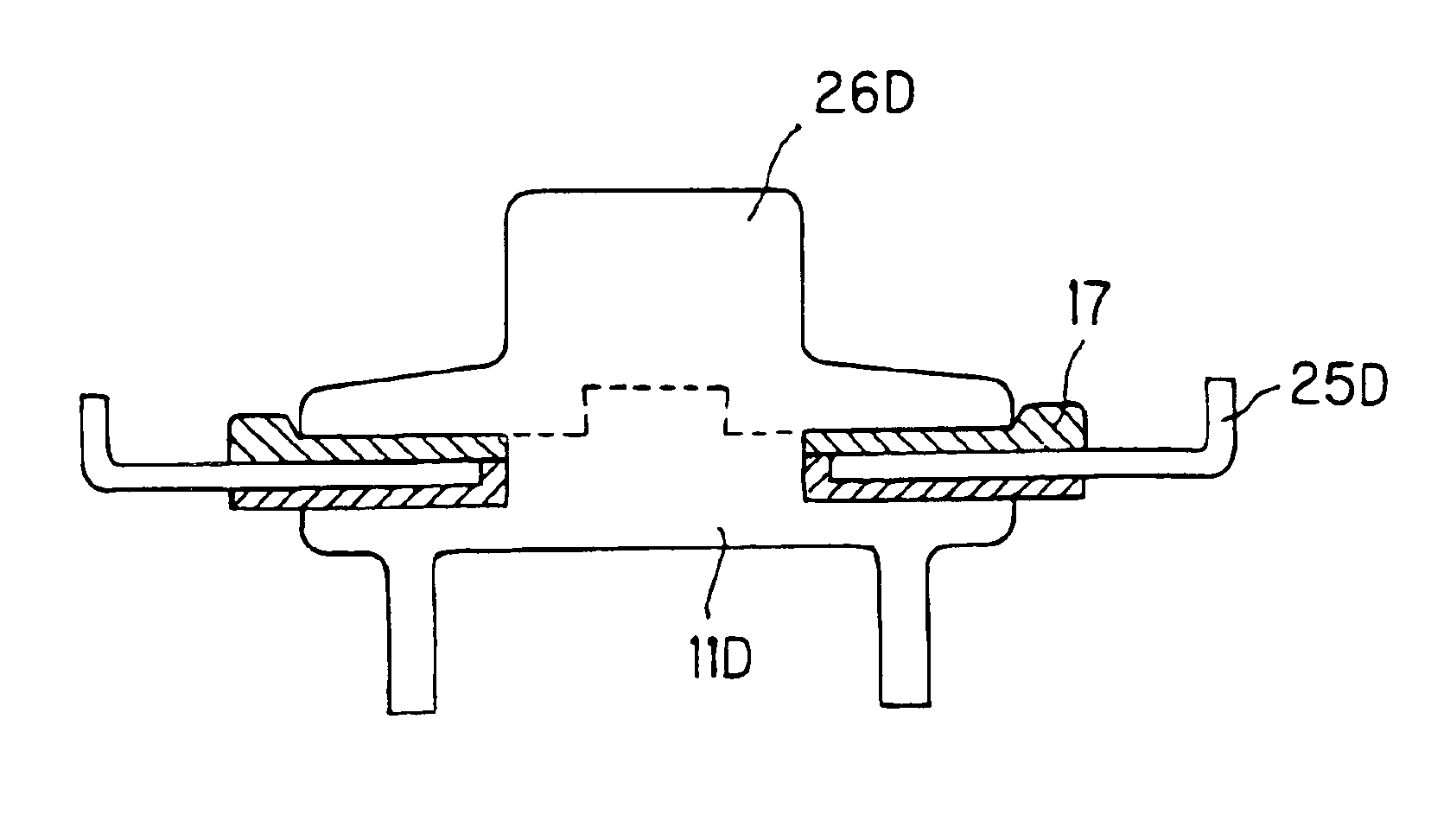
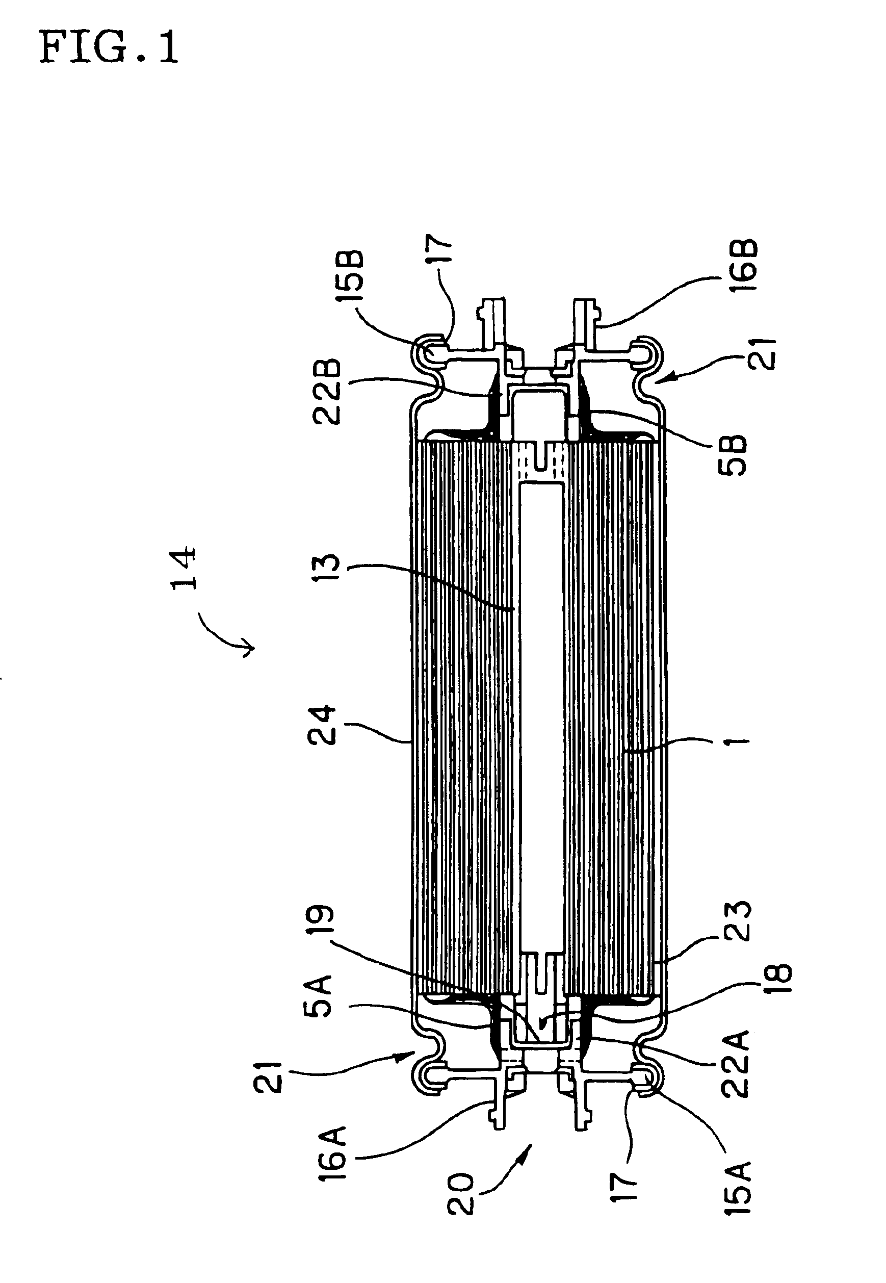
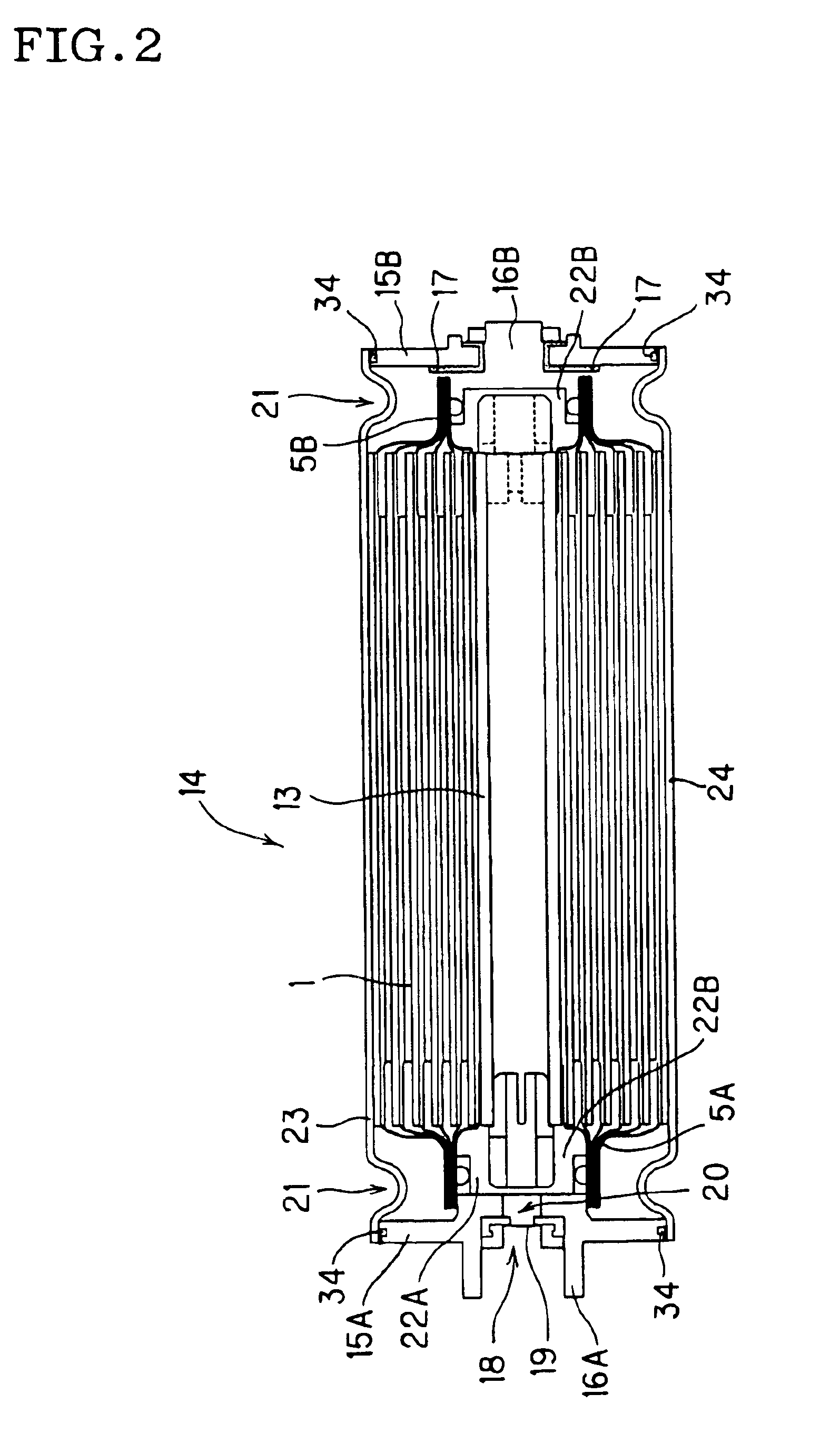
A lithium secondary cell of the first aspect in the present invention is a lithium secondary cell which comprises an internal electrode body including a hollow cylindrical winding core, a positive electrode plate and a negative electrode plate wound around an external peripheral wall of the hollow cylindrical winding core with a separator disposed therebetween, a nonaqueous electrolyte solution impregnating inside the internal electrode body; a cylindrical cell case being open...


PUM

PropertyMeasurementUnit
temperatureaaaaaaaaaa
pressureaaaaaaaaaa
currentaaaaaaaaaa

Abstract

To provide a lithium secondary cell, which is excellent in productivity since a cell structure is simple and easy for assembly. Provided is a lithium secondary cell having: an internal electrode body including a positive electrode plate, a negative electrode plate, the positive electrode plate and the negative electrode plate being wound and laminated around an external periphery wall of a hollow cylindrical winding core, and inside the internal electrode body a nonaqueous electrolyte solution being impregnated, a cylindrical cell case contained in this internal electrode body 1 with both ends being opened, and two electrode caps sealing the above described internal electrode body 1 at both the open ends of this cell case. The electrode cap has a plate member sealing the internal electrode body and disposed so as to seal both the open ends of the above described cell case, an external terminal member protruding onto the surface of the electrode caps to lead out currents to outside, and an internal terminal member brought into connection with the internal electrode body and taking out currents from the internal electrode body, and an elastic body and at least two of the above described plate member, the external terminal member and the internal terminal member are joined together for construction. Furthermore, there is also provided an assembly of lithium secondary cells.

Description

BACKGROUND OF THE INVENTION AND RELATED ART STATEMENTThe present invention relates to a lithium secondary cell (hereinafter also to be referred to simply as “cell”) and an assembly of lithium battery cells which comprises a plurality of lithium secondary cells and a plurality of bus bars (hereinafter also to be referred to simply as “assembly”) and particularly relates to a lithium secondary cell excellent in productivity and an assembly of lithium battery cells which comprises a plurality of lithium secondary cells and a plurality of bus bars excellent in output performance and productivity.In recent years, lithium secondary cells are widely used as a power source for electronic equipment such as portable communication equipment and a notebook-sized personal computer. In addition, requests for resource and energy savings are raised for the protection of the earth's environment on an international scale. The lithium secondary cell is being developed as a motor driving battery for an...

Claims


Application Information

Patent Timeline
Patent Type & Authority Patents(United States)
IPC IPC(8): H01M2/04H01M2/30H01M10/04H01M2/20H01M10/40H01M10/36H01M10/05H01M50/147H01M50/516H01M50/522H01M50/548H01M50/559H01M50/562H01M50/566H01M50/567
CPCH01M2/04H01M2/204H01M10/0431H01M2/30H01M10/05Y02E60/10H01M50/147Y02P70/50H01M50/522H01M50/562H01M50/559H01M50/516H01M50/567H01M50/566H01M50/548
Inventor ENOMOTO, AKIOKAWAMURA, KENJIKITOH, KENSHINYOSHIDA, TOSHIHIRONEMOTO, HIROSHIOTSUBO, SHINJI
Owner NGK INSULATORS LTD
Why Eureka
Try Eureka