Magnetic memory using perpendicular magnetization film

Inactive Publication Date: 2005-01-18
CANON KK
View PDF5 Cites 31 Cited by
  • Summary
  • Abstract
  • Description
  • Claims
  • Application Information

AI Technical Summary

Benefits of technology

There is also provided a method of manufacturing a magnetic memory having a magnetoresistive element in which a nonmagnetic layer is interposed between first and second magnetic layers formed from perpendicular magnetization films, a inversion field of the second magnetic layer is not smaller than a inversion field of the first magnetic layer, and a resistance value upon supplying a current between the first and second magnetic layers changes depending on a relative angle between magnetization directions of the first and second magnetic layers, comprising setting large saturation magnetization as at least the first magnetic layer is miniaturized.
There

Problems solved by technology

The magnetization direction of a recording/sustaining magnetic layer cannot settle and becomes unstable.
Hence, the magnetic thin-film memory having the above arrangement cannot save information at the same time as miniaturization of a bit ce

Method used


Image

  • Magnetic memory using perpendicular magnetization film
  • Magnetic memory using perpendicular magnetization film
  • Magnetic memory using perpendicular magnetization film

Examples


first embodiment

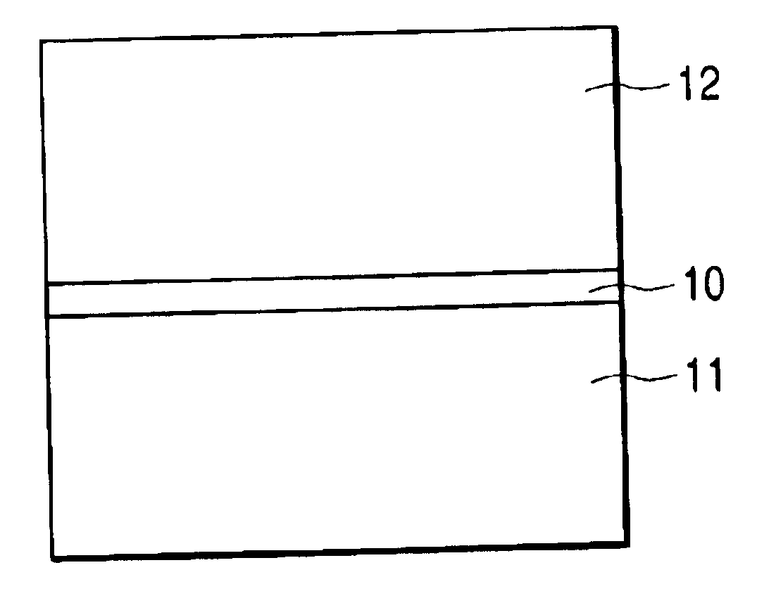
FIG. 7 shows a magnetoresistive element according to the first embodiment. The magnetoresistive element is constituted by stacking a first magnetic layer 11 formed from a perpendicular magnetization film, a nonmagnetic layer 10, and a second magnetic layer 12 formed from a perpendicular magnetization film. The inversion field of the second magnetic layer 12 is larger than that of the first magnetic layer 11. The resistance value upon supplying a current between the first and second magnetic layers 11 and 12 changes depending on the relative angle between the magnetization directions of the first and second magnetic layers 11 and 12. When the magnetoresistive element is used as an MRAM memory element, a magnetic field generation mechanism (not shown) is arranged to switch the magnetization direction of the first magnetic layer 11 of the magnetoresistive element.

To record information on this memory element, a magnetic field is applied to the magnetoresistive element by using the magne...

second embodiment

It is known that when a magnetic substance is miniaturized, magnetization switching occurs by heat energy at a given probability because of super paramagnetism. Super paramagnetism is a phenomenon that when miniaturization of the magnetic substance makes magnetic anisotropy energy equal to heat energy, each magnetic particle thermally vibrates like one atomic magnetic moment of paramagnetism.

Even if the magnetic substance is not miniaturized to a super paramagnetic size, magnetization switching occurs at a given probability of statistical mechanics, and destroys recorded information. This problem has been pointed out for recording media such as a hard disk.

The MRAM also suffers the same problem. In the perpendicular magnetization film, anisotropy energy is given by Ku−2πMs2×f, and f must be considered. Letting v be the volume of the magnetic film, a value Q: Q=v⁡(Ku-2⁢π⁢ ⁢Ms2⁢f)k⁢ ⁢Ta(7)

with respect to a temperature energy kT (k is the Boltzmann constant and Ta is the temperature) s...

example 1

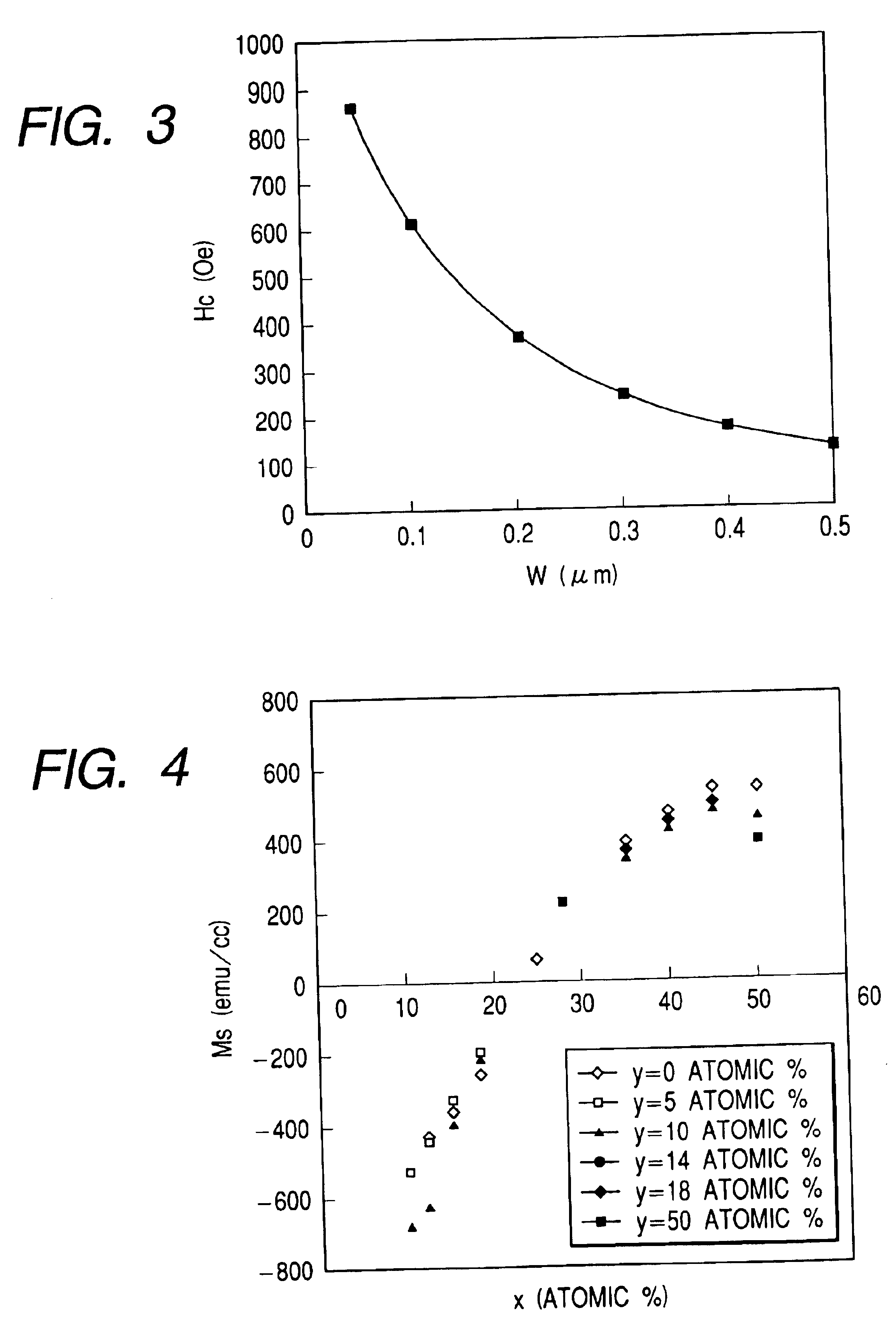
FIG. 5 and Table 1 show the inversion field Hc and Q when the saturation magnetization Ms is increased along with miniaturization of the magnetic film. The film thickness of the magnetic film is 50 nm. Q is v×(Ku−2πMs2) / (kT) where k is the Boltzmann constant of 1.38×10⁻¹⁶ erg / K, T is 298 K (room temperature), and v is the volume of the magnetic film (=W×W×film thickness). Q is a value representing the possibility of switching the magnetization of the magnetic substance by thermal agitation. No practical problem occurs as far as Q is 100 or more.

It is apparent from the results that the inversion field does not increase around 130 Oe even with a small width W. In addition, magnetization switching by thermal agitations is free from any problem.

In this manner, an increase in inversion field can be prevented by increasing the saturation magnetization along with downsizing using a ferrimagnet such as an alloy film of a rear-earth element and iron family element as a perpendicular magnetiz...


PUM


Abstract

In a magnetoresistive element of a magnetic memory, a inversion field Hc of at least a first magnetic layer is given by Hc=2(Ku-2πMs2f)Ms
where Ku and Ms are the perpendicular magnetic anisotropy constant and saturation magnetization of the first magnetic layer. The inversion field Hc is set smaller than a magnetic field generated by a magnetic field generation mechanism. Letting T be the film thickness of the first magnetic layer and W be the width and length, f is a factor given by
f=7×10⁻¹³(T/W)4−2×10−9(T/W)3+3×10−6(T/W)2−0.0019(T/W)+0.9681
A magnetic memory manufacturing method is also disclosed.

Description

BACKGROUND OF THE INVENTION1. Field of the InventionThe present invention relates to a magnetic thin-film element using a magnetoresistance effect such as a spin tunneling effect and an application of this element and, more particularly, to an application of a nonvolatile memory.2. Related Background ArtA magnetic thin-film memory is a solid-state memory having no movable portion, like a semiconductor memory. The magnetic thin-film memory is more advantageous than the semiconductor memory because the magnetic thin-film memory keeps information even upon power-off, has an infinite repetitive rewrite count, and is free from the risk of losing recording contents even by incident radiation. Recently, a thin-film magnetic memory using a spin tunneling (TMR) effect has received a great deal of attention because it can obtain a larger output than a conventional magnetic thin-film memory using an anisotropic magnetoresistance effect. These magnetic memories are called MRAMs (Magnetic Random...

Claims


Application Information

Patent Timeline
IPC IPC(8): G11C11/16G11C11/02H01F10/32H01F10/12H01F10/16H01L21/8246H01L27/105H01L43/08
CPCB82Y25/00G11C11/16H01F10/3286H01F10/3254H01F10/16H01F10/126G11C11/161G11C11/1675
Inventor NISHIMURA, NAOKI
Owner CANON KK
Why Eureka
Try Eureka