[0011]Another object of the invention is to provide
ceramic metal halide lamps of the Philips MasterColor® series that display excellent initial
color consistency, superb stability over life (
lumen maintenance >80%,
color temperature shift <200 K at 10,000 hrs), high
luminous efficacy of >90 lumens /
watt,
high color rendering index of >90, a lifetime of about 20,000 hours, and power ranges of about 150 W to about 1000 W, and in which the arc bending problem is eliminated or at least minimized, regardless of the orientation of the lamp in the fixture and regardless of the relative position of the frame wire to the arc tube.
[0012]Another object of the invention is to provide
ceramic metal halide lamps having a power range of about 150 W to about 1000 W and exhibiting one or more of a characteristic selected from the group consisting of a CCT (correlated
color temperature) of about 3800 to about 4500 K, a CRI (
color rendering index) of about 70 to about 95, a MPCD (mean perceptible
color difference) of about ±10, a
luminous efficacy up to about 85-95 lumens /
watt, in which the arc bending problem is eliminated or at least minimized, regardless of the orientation of the lamp in the fixture and regardless of the relative position of the frame wire to the arc tube.
[0014](1) at least two and preferably two straight frame wires, and utilized in ceramic
metal halide lamps. Preferably, a
wire frame structure is used in which identical straight frame wires extend adjacent and parallel on at least two sides of the arc tube. Preferably also the distance between the arc and each wire is equal. Placing the wires to extend parallel to and adjacent at least two sides of and
equidistant to the arc tube is believed to cancel the magnetic force acting on the arc. The current is carried by at least two wires at half of the intensity and the
magnetic field applied on the arc is cancelled out if the distances between the arc and the wires are equal. The
mount structure requires no more space than the
single frame wire structure commonly used in HPS lamps with a ED18
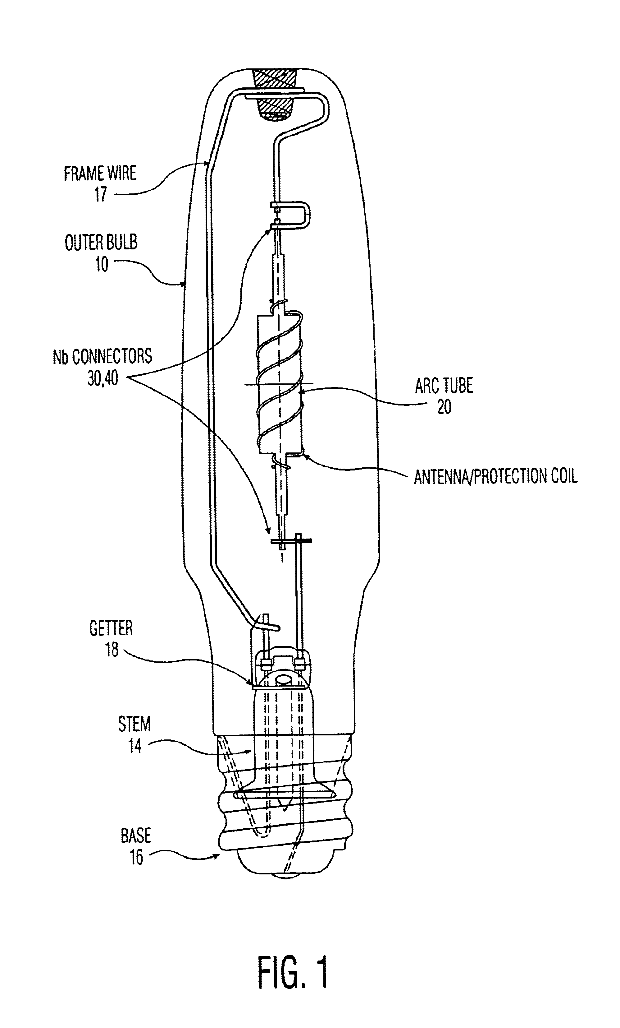
bulb, therefore the arc tubes can be mounted in elongated shaped standard glass bulbs such as ED18 illustrated in FIG. 1. This structure is suitable for lamps requiring a compact outer bulb. The cancellation of the
magnetic field in turn prevents arc bending and consequent heating of the PCA surface near the bent arc, regardless of the orientation of the lamp in the fixture and regardless of the relative position of the frame wire to the arc tube. This leads to improved life of the lamp.
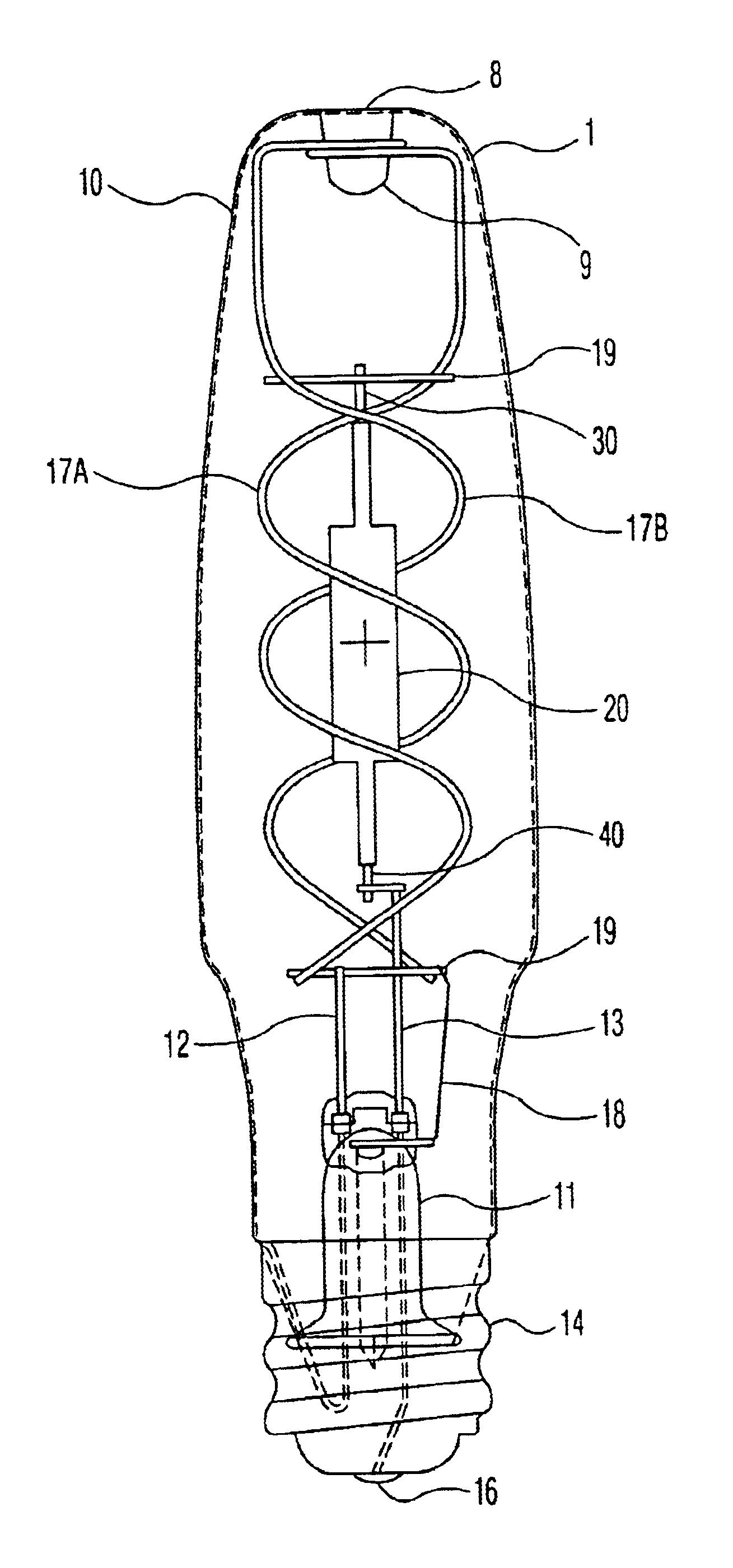
[0015](2) at least two and preferably two spirally curved frame wires, and utilized in ceramic metal halide lamps. Preferably, a
wire frame structure is used in which two identical spirally curved frame wires extend adjacent on two sides of the arc tube. Preferably also the distance between the arc and each wire is equal. Placing the arc tube in the common center of the two equally spaced spiral wires is believed to cancel the magnetic force acting on the arc. The current is carried by at least two wires at half of the intensity and the magnetic field applied on the arc is cancelled out if the distances between the arc and the wires are equal. The
mount structure requires no more space than the
single frame wire structure commonly used in HPS lamps with a ED18 bulb, therefore the arc tubes can be mounted in elongated shaped standard glass bulbs such as ED18. This structure is suitable for lamps requiring a compact outer bulb. The cancellation of the magnetic field in turn prevents arc bending and consequent heating of the PCA surface near the bent arc, regardless of the orientation of the lamp in the fixture and regardless of the relative position of the frame wire to the arc tube. This leads to improved life of the lamp.
[0016](3) at least one and preferably one spirally curved frame wire, and utilized in ceramic metal halide lamps. Preferably, a wire frame structure is used in which spirally curved frame wire extends on sides of the arc tube. Preferably also the distance between the center of the arc to the spiral is equal in all directions. Placing the spirally curved wires to extend to the arc tube is believed to alter the direction of the magnetic field to parallel to the arc. The current is carried by the spirally curved wire and the magnetic force applied on the arc is zero. The
mount structure requires no more space than the
single frame wire structure commonly used in HPS lamps with a ED18 bulb, therefore the arc tubes can be mounted in elongated shaped standard glass bulbs such as ED18. This structure is suitable for lamps requiring a compact outer bulb. The cancellation of the magnetic field in turn prevents arc bending and consequent heating of the PCA surface near the bent arc, regardless of the orientation of the lamp in the fixture and regardless of the relative position of the frame wire to the arc tube. This leads to improved life of the lamp.
[0017]In preferred embodiments of the invention, the lamps will exhibit one or more of the common characteristics of higher wattage MasterColor® lamps: excellent initial
color consistency; and / or superb stability over life (
lumen maintenance >80%,
color temperature shift <200 K at 10,000 hrs); and / or high
luminous efficacy of >90 lumens /
watt; and / or
color rendering index (CRI) of >90; and / or a lifetime of about 20,000 hours; and / or power ranges of about 150 W to about 1000 W; and in each instance, will employ at least one of the preferred embodiments of the invention, i.e. a curved frame wire as illustrated and described which extends adjacent the glass bulb and is effective to at least minimize arc bending when the lamp is operated; and / or lamps are provided having a power range of about 150 W to about 1000 W and exhibiting one or more of a characteristic selected from the group consisting of a CCT (correlated color temperature) of about 3800 to about 4500 K, a CRI (
color rendering index) of about 85 to about 95, a MPCD (mean perceptible
color difference) of about ±10, a luminous
efficacy up to about 85-95 lumens / watt, in which the arc bending problem is eliminated or at least minimized, regardless of the orientation of the lamp in the fixture and regardless of the relative position of the frame wire to the arc tube.

